
Visual planning diagrams, feeder examples, and sub-panel layout concepts for Minnesota shops, outbuildings, and garages.
In our primary Pole Barn Electrical Service Guide, we covered the critical structural rules, capacity considerations, and permit requirements for wiring outbuildings. However, when it comes to the actual trenching, conduit runs, and sub-panel connections, nothing beats a clear visual roadmap.
This guide provides visual pole barn wiring diagrams for three common outbuilding setups we see in West Central Minnesota. Below, you’ll find planning blueprints for sub-panel configurations, underground feeder sizes, grounding systems, and specific workshop tool circuits. Whether you’re working with building inspectors in Willmar, Benson, Morris, or rural Redwood County, these layouts will help you understand the scope of work before your electrician arrives.
- All diagrams and specifications in this guide are general planning examples only. They’re intended to help property owners understand planning concepts and scope of work – they aren’t a substitute for a permitted electrical design or installation by a qualified electrician.
- Final design depends on your specific load calculation, conductor type, temperature rating, voltage drop, raceway fill, equipment terminal ratings, site conditions, and the adopted code cycle enforced by your inspector.
- In Minnesota, outbuilding electrical work should be properly permitted and inspected. Bright Haven Electric coordinates with the appropriate electrical inspector before work begins.
1. Feeder Trenching & Conduit Diagram
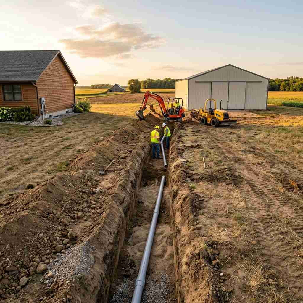
Before looking at sub-panels, the primary connection between your main residential panel, service disconnect, meter-main, or other property service equipment and your outbuilding must be properly designed. Below is a typical cross-section for an underground feeder conduit trench. Burial depth requirements vary by wiring method, voltage, and location – your inspector and installation details control the final requirement.
- Frost Depth: Minnesota winters freeze the ground 42 to 48 inches deep. While NEC burial depth for PVC conduit is often 18 inches, local inspectors commonly expect an expansion fitting where PVC emerges from underground and attaches to the building. This prevents winter ground heaving from cracking the conduit or pulling the sub-panel off the interior stud wall.
- Conduit vs. Direct Burial: Direct burial (UF-B cable) generally requires deeper cover and has limited protection from rocks, spade shovels, or rodents. Running individual wet-location-rated THWN-2 conductors inside Schedule 40 PVC conduit is significantly safer, has longer life expectancy, and allows you to pull larger conductors later if your workshop power demands increase. Long conduit runs, multiple bends, and future expansion plans may require larger conduit, pull boxes, or revised conductor sizing to comply with conduit-fill and pulling requirements.
- Four-Wire Feeder: A detached outbuilding sub-panel is typically fed with a four-wire feeder: two ungrounded (hot) conductors, one insulated neutral, and one equipment grounding conductor (EGC). The neutral and ground are bonded only at the main service equipment – not in the detached sub-panel. See NEC 250.32(B)(1).
2. Sub-Panel Neutral & Ground Separation Diagram
The most common reason DIY electrical installations fail inspection in Minnesota is the incorrect bonding of the neutral and grounding buses inside the outbuilding sub-panel. Under the National Electrical Code, the neutral bus in a detached outbuilding sub-panel must remain isolated from the equipment grounding conductors and panel cabinet. Detached buildings also generally require a disconnecting means at the structure – in many installations, a main breaker in the outbuilding panel serves this purpose.
Why must grounds and neutrals remain isolated? In your main electrical service equipment, neutrals and equipment grounds are bonded together at the service disconnect. However, in a detached structure, if you connect the neutral bus bar to the metal sub-panel case, you create a parallel return path for normal operating electricity. A portion of the return current will constantly flow through the equipment grounding conductor, metal raceways, and structural steel of the pole barn – causing unexpected voltage on metal surfaces, tripping GFCI breakers, and creating dangerous stray voltage in livestock facilities.
3. Three Standard Workshop Wiring Configurations
Here are planning layouts for three common outbuilding configurations we see throughout Kandiyohi, Swift, Stevens, and Redwood counties.
| Setup Type | Sub-Panel Size | Planning Example Feeder Size – Up to 150’ | Grounding Electrode Requirement | Best For |
|---|---|---|---|---|
| Basic Hobby Garage | 60 Amp, main breaker preferred (main-lug allowed only when disconnect rules are met) | #6 AWG Copper (in PVC) | Grounding electrode system, typically 2 ground rods | Hobby benches, basic lawn equipment, single table saws |
| The Mechanic’s Shop | 100 Amp (Main Breaker) | #2 AWG Copper or 1/0 Aluminum | Grounding electrode system, typically 2 ground rods | 240V air compressors, MIG/TIG welders, vehicle lifts |
| Agricultural/Commercial | 200 Amp (Main Breaker) | 4/0 AWG Copper or 250 kcmil Aluminum (typical) | Grounding electrode system + metal structure bonding + concrete-encased electrode, often called a Ufer, if present | Continuous heavy machinery, grain bins, vehicle fleets |
Planning Notes for All Configurations
- Load calculation required: Panel size should be selected after calculating expected loads – including heating, welders, compressors, vehicle lifts, lighting, EV charging, well pumps, grain-bin equipment, and future expansion.
- Feeder sizes are planning examples only. Final conductor sizing depends on load calculation, conductor material, insulation type, temperature rating, voltage drop, raceway fill, equipment terminal ratings, and inspector requirements.
- GFCI protection: Under NEC 210.8, garages, accessory buildings, outdoor locations, and many shop/outbuilding receptacles require GFCI protection. Newer NEC rules also extend GFCI protection to certain higher-amperage and 240V receptacles, including some 240V receptacles up to 50A depending on location and use. Welder and compressor receptacles should be reviewed during design to confirm the correct GFCI requirements with the electrician and inspector.
- Metal building bonding: Metal building components, structural steel, and other conductive systems may need to be bonded to the grounding system regardless of building size – not just 200A agricultural setups.
- Concrete-encased electrodes: If the outbuilding is being constructed with a new concrete foundation containing structural rebar, a connection to a concrete-encased electrode (often called a Ufer ground) per NEC 250.50 is required – this connection must be made before the concrete is poured. It isn’t optional when the electrode is present at the building.
- Surge protective devices: Current NEC rules require surge protection in certain dwelling-unit service or feeder situations, and outbuildings housing sensitive equipment – VFDs, tool battery chargers, LED drivers, or shop electronics – can benefit significantly from surge protection at the sub-panel. We recommend installing an SPD at the outbuilding panel as a best practice when appropriate, even when not strictly required for that specific installation.
- Detached-building disconnect clarification: Detached buildings generally require a disconnecting means at the structure. In many installations, a main breaker in the outbuilding panel serves this purpose. Main-lug panel designs with six or fewer breakers should be reviewed carefully with the inspector before installation because service disconnect rules and detached-building feeder disconnect rules are found in different NEC articles.
Setup A: The 60-Amp Basic Hobby Garage
Ideal for vehicle storage, seasonal workshops, and basic lawn care maintenance. This configuration utilizes a 60A panel fed from a 60A breaker at the home or property’s main electrical equipment. If using a main-lug-only panel, the design generally needs six or fewer circuit breakers to satisfy the detached-building disconnect rules under NEC 225.33 – otherwise, use a main breaker panel or install a separate disconnect.
Setup B: The 100-Amp Mechanic’s Workshop
Designed for heavy fabrication, restoration, and mechanical workshops. This setup handles high-load tools like stationary air compressors and professional welders running simultaneously.
Setup C: The 200-Amp Agricultural or Commercial Outbuilding
Designed for large shops, grain-bin support equipment, fleet maintenance, commercial storage buildings, and heavy machinery loads. This setup usually requires a detailed load calculation, larger feeder conductors, metal building bonding review, surge protection planning, and coordination with the electrical inspector before trenching or panel installation.
4. Outbuilding Grounding Electrode Layout
Per NEC 250.32, a detached outbuilding generally needs both an equipment grounding conductor (EGC) run with the feeder and a grounding electrode system at the building. The feeder EGC provides the low-impedance fault path needed for breaker operation, while the grounding electrode system connects the detached structure to earth and helps stabilize the electrical system during lightning, surges, and abnormal voltage conditions.
Dual Ground Rod Rule
Most detached outbuilding installations use two copper-clad or galvanized steel ground rods, unless a single grounding electrode is proven to have 25 ohms or less resistance to ground (which is rare in Minnesota’s variable soils). Each rod must be a minimum of 8 feet in length. The rods are typically driven flush with or below grade, or otherwise protected from physical damage, so clamps aren’t exposed to lawn equipment or frost movement.
8-Foot MinimumThe 6-Foot Stagger
To establish a broad, reliable electrical ground plane, the two ground rods must be spaced at least 6 feet apart. Driving them closer causes their spheres of influence to overlap, reducing the effectiveness of the grounding electrode system – especially in dry or sandy soil. A #6 AWG copper grounding electrode conductor is commonly run from the sub-panel ground bar to the rods, with any splices or connections made only by approved methods (irreversible compression connectors or exothermic welding per NEC 250.64(C)).
6-Foot Spacing“Whenever we inspect pole barns, we frequently see homeowners driving a single 8-foot copper rod or clamping their ground wire directly to the metal building frame without proper ground rods. This is a serious safety concern. If the metal building frame isn’t properly bonded to the equipment grounding system, a fault can leave metal parts energized or delay proper fault clearing. Ground rods are required, but they don’t replace the equipment grounding conductor run with the feeder – both are needed for a safe installation.” – Chadwick Ferguson, Co-Owner, Bright Haven Electric
Local Outbuilding Electricians – West Central Minnesota
Bright Haven Electric LLC coordinates complete pole barn electrical planning, layout, trenching, wiring, and inspection coordination across West Central Minnesota. Our local office handles direct coordination with the appropriate electrical inspector so your workshop, storage shed, or commercial barn is ready for inspection.
We provide full-service outbuilding wiring in these communities:
Get an Inspected, Safe Pole Barn Layout
Avoid expensive rework or inspection failures. Let our licensed electricians plan and install your pole barn wiring according to current code requirements and site-specific inspection standards.
In a detached building sub-panel, keeping neutrals and grounds separate is required by code to prevent neutral return current from flowing through equipment grounding conductors, metal raceways, pipes, or structural steel. The bonding link must be removed, isolating the neutral bus from the panel cabinet.
For many common residential PVC conduit feeder installations, NEC Table 300.5 generally requires 18 inches of cover from the top of the conduit to finished grade, with deeper cover often required under driveways or vehicle traffic areas. Burial depth requirements vary by wiring method, voltage, and specific installation conditions – your inspector and installation details control the final requirement.
Most detached outbuilding sub-panels use two grounding electrodes (ground rods) unless a single rod is tested and proven to have 25 ohms or less resistance to ground. In practice, two 8-foot rods spaced at least 6 feet apart are commonly installed because soil resistance testing is rarely practical for typical residential and farm outbuildings in Minnesota.
Pole Barn & Outbuilding Wiring Guide
Sub-panel sizing, underground feeder runs, circuit planning, and NEC code requirements for pole barns, shops, and outbuildings in West Central Minnesota.
Every spring and summer across West Central Minnesota, property owners build pole barns, machine shops, detached garages, and agricultural outbuildings. The structure goes up fast – but the electrical service is where most projects stall, get quoted wrong, or end up with code violations that fail inspection. Pole barn wiring isn’t the same as house wiring. The distances are longer, the loads are heavier, the environment is harsher, and the NEC requirements are specific.
This guide covers what you need to know before the electrician arrives – and what a licensed pole barn electrician should be doing when they get there. Whether you’re building a 30×40 hobby shop or a 60×120 machine shed with three-phase welders, the fundamentals are the same. Get the service right, size the feeder correctly, plan your circuits before the slab is poured, and you’ll have an outbuilding that works as hard as you do.
Bright Haven Electric has wired pole barns, shops, and agricultural outbuildings across our 10-county service area for over two decades. This guide reflects what we see in the field – not theory from a textbook.
Planning Your Outbuilding Electrical Service
The single most important decision in pole barn wiring happens before a single wire is pulled: how much power do you need – now and in five years? Undersizing the service to save money today guarantees an expensive upgrade later. Here is how to think about it:
Sub-Panel Sizing
A hobby shop with lighting and a few outlets needs a 60-amp sub-panel minimum. A working shop with a welder, air compressor, and dust collection needs 100 amps. A full machine shop or agricultural building with three-phase equipment typically requires 200 amps or a dedicated transformer. Always size for what you’ll need in five years – not what you need today. For high-demand farm shops or grain-handling sites, integrating dedicated irrigation VFD upgrades provides critical energy savings and voltage stabilization.
Size for GrowthUnderground Feeder Runs
Most pole barns require an underground feeder from the house panel or meter to the outbuilding sub-panel. NEC requires direct-burial cable (UF-B) at 24″ depth minimum, or conduit (PVC Schedule 40 or rigid) at 18″ minimum. Longer runs mean larger wire to compensate for voltage drop – a 200-foot run at 100 amps typically requires 1/0 AWG copper or 2/0 aluminum.
Voltage Drop MattersCircuit Planning
Plan your circuits before the concrete is poured and the metal is up. Welding outlets (50A/240V), air compressor (30A/240V), dust collection, overhead lighting, convenience outlets, and exterior security lighting all need dedicated or shared circuits planned from the start. Running conduit through a finished pole barn ceiling is ten times harder than stubbing it up through the slab.
Plan Before You PourGrounding & Bonding
Outbuilding sub-panels require a separate grounding electrode system – typically two ground rods driven at least 6 feet apart. The neutral and ground buses must be separated in the sub-panel (unlike the main panel). This is the most commonly failed inspection item on outbuilding wiring. Metal buildings also require bonding of the steel frame to the grounding system.
Top Inspection Failure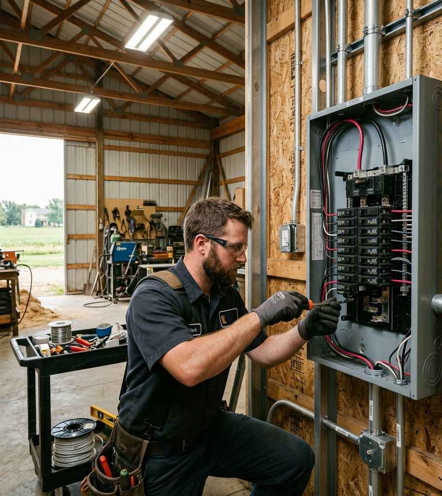
Common Pole Barn Electrical Configurations
Not every pole barn needs the same service. Here are the four most common configurations we install across West Central Minnesota, from basic to full commercial:
Configuration 1: Basic Hobby Shop (60A Service)
The Weekend Workshop
For woodworking, small projects, vehicle storage with lighting, and seasonal use. Typical building: 24×32 to 30×40.
- 60-amp sub-panel – 12 to 16 spaces, fed from the house main panel
- 4 – 6 general-purpose 20A circuits – outlets around the perimeter at workbench height
- 2 dedicated lighting circuits – overhead LED high-bays and task lighting
- 1 exterior circuit – security lighting and a weatherproof outlet
- GFCI protection – required on all receptacles in an unfinished building (NEC 210.8)
Configuration 2: Working Shop (100A Service)
The Serious Workshop
For welding, fabrication, automotive work, and heavy-duty power tools. Typical building: 30×50 to 40×60.
- 100-amp sub-panel – 20 to 30 spaces, dedicated feeder from the meter or main panel
- 1 – 2 welding outlets (50A/240V NEMA 6-50) – dedicated circuits for MIG, TIG, or stick welders
- 1 air compressor circuit (30A/240V) – for a 5 – 7.5 HP stationary compressor
- 6 – 8 general-purpose 20A circuits – outlets on all walls, including ceiling drops
- Dust collection circuit (20A/240V) – if running a central dust system
- LED high-bay lighting – 2 circuits, typically 8 – 12 fixtures for proper coverage
- Exterior security lighting – motion-activated LED floods on all four corners
Configuration 3: Agricultural Building (200A Service)
The Farm Machine Shop
For full-scale farm operations – equipment maintenance, grain handling support, livestock infrastructure. Typical building: 40×80 to 60×120.
- 200-amp sub-panel or dedicated meter – may require utility coordination for a new service drop
- Multiple 240V circuits – welders, plasma cutters, hydraulic presses, and large compressors
- Three-phase power – required for equipment like large lathes, milling machines, and grain handling motors
- Phase converter or VFD – if utility three-phase isn’t available at the site (common in rural MN)
- Agricultural ventilation circuits – exhaust fans, heaters, and environmental controls
- Fuel pump and grain dryer circuits – dedicated, code-compliant, with proper disconnect switches
- Explosion-proof fixtures – required in areas with combustible dust or fuel vapors per NEC Article 500
Configuration 4: Commercial Outbuilding (200A+ / 3-Phase)
The Commercial Operation
For commercial shops, fleet maintenance, contract manufacturing, or agricultural processing. Requires engineered plans and utility coordination.
- 400-amp+ service or dedicated transformer – utility will size based on your load calculation
- Three-phase distribution panel – for motors, CNC equipment, and industrial compressors
- Fire alarm and emergency lighting – required for commercial occupancy per Minnesota State Building Code
- Code-required disconnects – at all equipment, at the building entrance, and at the meter
- Engineered load calculation – required by the State Electrical Inspector before the permit is issued
“The number one mistake I see is someone who builds a beautiful 40×60 shop, puts in a 60-amp panel to save a few hundred dollars, and then calls us a year later because they can’t run their welder and compressor at the same time. We upgrade more undersized outbuilding panels than anything else. Size it right the first time – the wire in the ground is the expensive part, not the panel.” – Chadwick Ferguson, Master Electrician & Co-Owner, Bright Haven Electric LLC
NEC Code Requirements for Outbuilding Wiring
Minnesota enforces the 2023 National Electrical Code (NEC) statewide. Pole barns, detached garages, and agricultural outbuildings fall under specific NEC articles that differ from residential house wiring. Here are the code requirements that matter most:
Critical NEC Articles for Outbuildings
- Separate grounding electrode required (NEC 250.32). Every detached building with a sub-panel must have its own grounding electrode system – minimum two ground rods, 8 feet long, driven at least 6 feet apart. The neutral and ground buses must be isolated in the sub-panel. This isn’t optional and is the most common inspection failure.
- GFCI protection on all 125V receptacles (NEC 210.8). In unfinished spaces – which includes most pole barns – every 15A and 20A, 125V receptacle requires GFCI protection. This applies to interior and exterior outlets. Use GFCI breakers in the sub-panel for the cleanest installation.
- Disconnecting means at the building (NEC 225.31). The outbuilding must have a disconnect switch or main breaker at or near the point where the feeder enters the building. A main-breaker sub-panel satisfies this requirement. A main-lug-only panel doesn’t – you would need a separate disconnect.
- Underground feeder burial depth (NEC Table 300.5). Direct-burial UF-B cable requires 24″ minimum cover. PVC conduit requires 18″ minimum. Rigid metal conduit requires 6″ minimum. Under driveways, concrete, or areas subject to vehicle traffic, add 6″ to all minimums. We always recommend conduit over direct burial – it protects the wire and allows future upgrades without re-trenching.
- Voltage drop calculation (NEC 210.19 Informational Note). NEC recommends no more than 3% voltage drop on branch circuits and 5% total from the utility transformer to the outlet. On a 200-foot run, this often requires upsizing the feeder conductor by one or two sizes. A 100-amp feeder at 200 feet in aluminum typically needs 2/0 AWG minimum – not the #2 that ampacity tables alone would allow.
- Agricultural building requirements (NEC Article 547). Buildings housing livestock, storing hay, or handling grain are classified as agricultural buildings and require specific wiring methods: dust-tight and corrosion-resistant equipment, proper separation of grounding and bonding conductors, and equipotential bonding planes in livestock confinement areas to prevent stray voltage.
5 Costly Mistakes to Avoid
After wiring hundreds of outbuildings, we see the same mistakes repeated. Each one costs more to fix after the fact than it would have cost to do correctly from the start:
Undersized Service
Installing a 60-amp panel when a 100-amp is needed saves $200 today and costs $3,000 to upgrade later – because the underground feeder has to be replaced too. The panel itself is the cheapest component. The trench and wire are the expensive parts. Size it right once.
Most Common MistakeNo Permit or Inspection
Minnesota requires an electrical permit for all new outbuilding wiring. Skipping the permit means no inspection – which means no one checks whether the grounding, feeder sizing, and GFCI protection meet code. Insurance companies can deny fire claims on unpermitted electrical work. It isn’t worth the risk.
Insurance RiskBonding the Neutral in the Sub-Panel
In a sub-panel, the neutral bus and ground bus must be separated – the bonding screw or strap must be removed. Bonding neutral to ground in a sub-panel creates parallel paths for current on the grounding conductor, which can energize metal building frames and cause stray voltage on livestock operations.
Shock & Stray Voltage HazardIgnoring Voltage Drop
A 150-foot underground run with undersized wire delivers low voltage to your equipment. Your welder arcs weakly, your compressor motor overheats, and your LED lights flicker. Voltage drop isn’t a suggestion – it’s physics. Calculate it before you buy wire, or your electrician will do it for you.
Equipment Damage RiskPoor Lighting Layout
Putting two light fixtures in a 40×60 shop creates shadows everywhere you actually work. LED high-bays are inexpensive – plan for 50+ lumens per square foot in work areas. Mount them on separate circuits from outlet circuits so a tripped breaker doesn’t leave you in the dark with a running saw.
Easy to Get RightA Note on DIY Pole Barn Wiring
- Minnesota law allows homeowners to wire their own primary residence – but outbuildings and detached structures still require a licensed electrician in many jurisdictions
- Even where homeowner wiring is permitted, the State Electrical Inspector still inspects the work to the same NEC standard as a licensed contractor
- Sub-panel installations, underground feeder runs, and three-phase work involve calculations and techniques that aren’t covered in DIY guides – mistakes create fire and shock hazards that may not be apparent for months or years
- Insurance companies increasingly require proof of permitted, inspected electrical work for outbuilding coverage – unpermitted work can void your policy
Pole Barn Electricians – West Central Minnesota
Bright Haven Electric LLC wires pole barns, machine shops, and agricultural outbuildings across West Central Minnesota. From a 30×40 hobby shop near Glenwood to a 60×120 machine shed outside Granite Falls, we handle the full scope – underground feeder, sub-panel, circuits, lighting, and inspection coordination.
We serve property owners across our 10-county service area:
Building a Pole Barn? Get the Electrical Right.
From sub-panel sizing to underground feeder runs, we handle the full scope of outbuilding electrical – permitted, inspected, and built to last. Request a quote before you break ground.
It depends on how you use the building. A basic hobby shop needs a 60-amp sub-panel minimum. A working shop with a welder and compressor needs 100 amps. An agricultural building or machine shop with three-phase equipment typically requires 200 amps or more. Always size for future use – upgrading the underground feeder later costs significantly more than installing the right size initially. A licensed electrician will perform a load calculation to determine the correct size for your specific equipment list.
Per the 2023 NEC Table 300.5, direct-burial cable (UF-B) requires a minimum of 24 inches of cover. PVC conduit requires 18 inches minimum. Rigid metal conduit requires only 6 inches. Under driveways or areas with vehicle traffic, add 6 inches to all minimums. We recommend PVC conduit over direct burial because it protects the wire from damage and allows future conductor upgrades without re-trenching.
Yes. Minnesota requires an electrical permit for all new outbuilding wiring, including pole barns, detached garages, and agricultural buildings. The work must be inspected by the Minnesota State Electrical Inspector and pass to the current NEC code. Skipping the permit means no inspection – and insurance companies can deny claims on unpermitted electrical work. Contact Bright Haven Electric and we handle the permit process as part of the project.
Yes. Per NEC 250.32, every detached building with a sub-panel requires its own grounding electrode system – typically two ground rods, 8 feet long, driven at least 6 feet apart. The neutral bus and ground bus in the sub-panel must also be separated (the bonding screw must be removed). This is the most commonly failed inspection item on outbuilding wiring projects.
Costs vary significantly based on the service size, feeder run distance, and circuit count. A basic 60-amp hobby shop with a short underground run typically costs $2,500-$4,500. A 100-amp working shop with welding outlets runs $5,000-$9,000. A 200-amp agricultural building with three-phase power can range from $10,000-$20,000+ depending on equipment requirements and utility coordination. Request a detailed estimate – we provide transparent, itemized quotes for every project.
Why Are My Lights Flickering?
8 real causes – from a 10-second bulb fix to a failing service neutral that could burn your house down. Know when to fix it yourself and when to call a licensed electrician.
Flickering lights are one of the most common electrical complaints homeowners bring to us – and one of the most misunderstood. A light that flickers once when the AC kicks on isn’t the same problem as lights that dim across half your house during a windstorm. One is a minor nuisance. The other is a symptom of a life-threatening electrical failure happening right now inside your walls or at your service entrance.
The challenge is that flickering lights have at least eight distinct causes, and they range from a 10-second DIY fix (tighten a loose bulb) to an emergency that requires your utility company and a licensed electrician immediately. This guide walks you through every cause, shows you how to identify which one you’ve, and tells you exactly when it’s safe to fix it yourself – and when it isn’t.
If you’re experiencing flickering or dimming lights right now, start with the 3 emergency patterns below before reading the full guide. Some flickering patterns require immediate action.
The 8 Real Causes of Flickering Lights
We’ve organized these from simplest (fix it yourself in seconds) to most dangerous (call immediately). Each card tells you the cause, what you’ll see, and whether it’s a DIY fix or a job for a licensed electrician.
1. Loose or Wrong-Type Bulb
What you see: A single light flickers intermittently. Other lights in the room are fine. The fixture works normally with a different bulb.
Why it happens: The bulb isn’t fully seated in the socket, or you’re using an incompatible LED bulb in a fixture designed for incandescent. Some cheap LED bulbs also flicker at the end of their lifespan due to failing driver circuits.
The fix: Turn the light off, let the bulb cool, and tighten it. If it’s an LED, try a different brand – look for “dimmable” or “flicker-free” on the packaging.
2. Dimmer Switch Incompatibility
What you see: LED bulbs flicker constantly or buzz when connected to a dimmer switch. The flickering may change intensity as you adjust the dimmer.
Why it happens: Older dimmer switches were designed for incandescent bulbs and use a technology called TRIAC dimming. Many LED bulbs require a different dimming method. When the dimmer and bulb are incompatible, the LED driver can’t maintain a stable output and the bulb flickers or strobes.
The fix: Replace the dimmer with an LED-compatible dimmer switch. Check the LED manufacturer’s compatibility list. This is a straightforward swap if you’re comfortable working with switches – otherwise call a pro.
3. Overloaded Circuit
What you see: Lights dim briefly when a high-draw appliance turns on – a space heater, hair dryer, microwave, or window AC unit. The dimming lasts 1 – 2 seconds and then the lights return to normal.
Why it happens: The appliance draws a large inrush current when its motor or heating element starts. If the appliance shares a circuit with the lights, the sudden current draw causes a brief voltage drop on that circuit, and the lights dim momentarily.
The fix: Occasional, brief dimming on the same circuit as a large appliance is usually normal. However, if the dimming is severe, affects other circuits, or the breaker trips, the circuit is overloaded. A licensed electrician can install a dedicated circuit for the high-draw appliance.
4. Loose Wiring at Outlet or Fixture
What you see: A specific light fixture or outlet flickers, buzzes, or works intermittently. The problem seems localized to one point. Jiggling the fixture or outlet may change the flickering.
Why it happens: A wire connection inside the outlet box, switch box, or light fixture junction box has come loose. Loose connections create high-resistance points where electricity arcs across the gap. This generates heat and is a leading cause of electrical fires.
The fix: Don’t ignore this. A loose connection that arcs is a fire hazard. Call a licensed electrician to open the box, identify the loose connection, and re-terminate it properly. This isn’t a DIY repair – live wiring is involved.
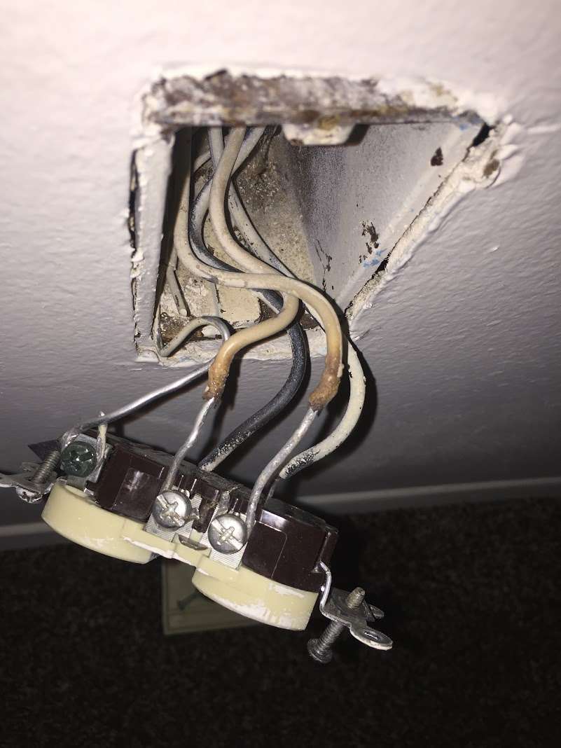
5. Aluminum Wiring Connections Oxidizing
What you see: Lights flicker in multiple rooms, often worsening over months or years. Outlets feel warm. Switches make crackling sounds. The home was built between 1965 and 1975.
Why it happens: Homes wired with aluminum branch circuit wiring develop oxide buildup at every connection point. Aluminum expands and contracts more than copper with each heating cycle, loosening connections over time. The oxide layer increases resistance, which generates more heat, which loosens connections further – a progressive failure cycle that ends in fire.
The fix: A licensed electrician performs aluminum wiring remediation – installing AlumiConn connectors or COPALUM crimps at every connection point in the home. This is a multi-day project but eliminates the failure mechanism entirely.
6. Failing Circuit Breaker
What you see: Lights on one circuit flicker or dim repeatedly. The breaker may trip occasionally – or it may be warm to the touch. The flickering has gotten worse over time.
Why it happens: Circuit breakers have a finite lifespan. Internal contacts wear out, springs weaken, and the breaker loses its ability to maintain a solid connection with the bus bar. A breaker that’s loose in its bus slot or has corroded contacts creates an intermittent connection – the lights flicker as the circuit makes and breaks contact. See our guide to dangerous electrical panel warning signs.
The fix: A licensed electrician replaces the failing breaker and inspects the bus bar for damage. If the panel is a recalled brand, full panel replacement may be necessary.
7. Loose Service Entrance Neutral
What you see: Lights throughout the house flicker, dim, or surge – some getting brighter while others dim simultaneously. The flickering may worsen during wind or storms. Light bulbs burn out frequently. Electronics malfunction or die prematurely.
Why it happens: The neutral conductor at your service entrance (the connection between your panel and the utility transformer) has come loose or corroded. This causes an imbalanced voltage between the two 120V legs of your home’s electrical system. One leg gets over-voltage (lights get brighter, electronics fry) while the other gets under-voltage (lights dim). This is called a floating neutral or open neutral – and it’s an emergency.
The fix: Call your utility company AND a licensed electrician immediately. A floating neutral can send 180V+ through circuits designed for 120V, destroying appliances and creating extreme fire risk. Don’t wait.
8. Utility-Side Voltage Fluctuation
What you see: All lights in the house flicker simultaneously and briefly – usually for a fraction of a second. It happens at random, sometimes multiple times a day, sometimes weeks apart. Your neighbors may experience the same thing.
Why it happens: The utility’s transformer, distribution lines, or switching equipment is experiencing load fluctuations, tree contact, or equipment degradation. Storms, ice loading, and high-demand periods can exacerbate utility-side voltage sags. In rural West Central Minnesota, long distribution runs to remote properties are especially susceptible.
The fix: Report the issue to your electric cooperative or utility. If it persists, a whole-house surge protector will protect your electronics from voltage transients, and a power conditioning system can stabilize the voltage entering your home.
3 Flickering Patterns That Mean Call an Electrician NOW
- Lights dim AND brighten simultaneously in different rooms – This is the signature of a loose or open service neutral. Some circuits get over-voltage while others get under-voltage. Electronics are being damaged in real time. Call your utility company and a licensed electrician immediately
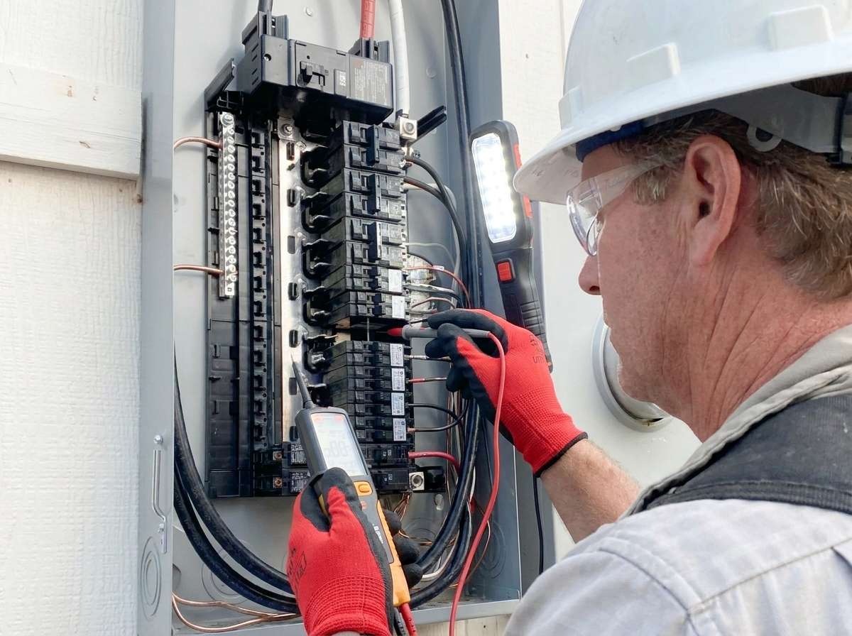
- Flickering accompanied by a burning smell, buzzing, or warm outlets/switches – These are signs of active arcing at a connection point. Arcing generates temperatures exceeding 10,000°F at the arc site – hot enough to ignite wood framing and insulation inside your walls. Turn off the affected circuit at the breaker panel and call a licensed electrician
- Flickering that’s getting progressively worse over weeks or months – Progressive flickering indicates a connection that’s deteriorating over time – typically aluminum wiring oxidation, a corroding bus bar connection, or a failing neutral. This won’t fix itself. It will continue to degrade until it causes a fire or equipment failure. Schedule an electrical safety inspection as soon as possible
What to Check First: Diagnostic Flowchart
Before you call an electrician, you can narrow down the cause significantly by answering a few questions. This diagnostic sequence is what we walk through on every flickering-lights service call:
- Is it one fixture or multiple?
If only one light flickers, the problem is local – check the bulb, the fixture, or the switch controlling it (Causes 1 – 2). If multiple lights flicker, skip to Step 3
- Does it happen on a dimmer?
If the flickering fixture is on a dimmer switch, replace the dimmer with an LED-compatible model before calling an electrician. This solves the majority of single-fixture flickering complaints (Cause 2)
- Does it happen when an appliance turns on?
If lights dim briefly when the AC, heater, or microwave starts – and only on the same circuit – this is likely an overloaded circuit (Cause 3). If the dimming affects lights on other circuits, the issue is at your panel or service entrance (Causes 6 – 7)
- Is it one circuit or the whole house?
If flickering is limited to one breaker’s circuit, the problem is a loose connection on that circuit or a failing breaker (Causes 4, 6). If the flickering is house-wide, go to Step 5
- Do some lights get brighter while others get dimmer?
This is the critical question. If yes – stop diagnosing and call your utility company and an electrician immediately. You’ve a loose or open neutral (Cause 7). If all lights flicker uniformly, it’s likely a utility-side issue (Cause 8)
- Was the home built between 1965 and 1975?
If yes, and you’re experiencing multi-room flickering, warm outlets, or crackling switches, you may have aluminum branch circuit wiring that’s oxidizing at connection points (Cause 5). This requires professional evaluation
“The call I dread most is the loose neutral. By the time the homeowner notices lights surging and dimming, the imbalanced voltage has already been cooking their electronics and appliances for hours or days. I have seen $15,000 in appliance damage from a single corroded neutral connection at the weatherhead. That’s why I tell people: if lights get brighter and dimmer at the same time in different rooms, don’t Google it – call your utility and call us. Right now.” – Chadwick Ferguson, Master Electrician & Co-Owner, Bright Haven Electric LLC
Related Guides
Flickering lights often lead to deeper electrical issues. These companion guides cover the most common next steps:
- Is Your Electrical Panel Dangerous? 7 Warning Signs – If your breaker is the cause, this guide covers recalled brands and when to replace your panel
- How to Reset a GFCI Outlet & Tripped Breaker – If flickering is accompanied by tripped breakers or dead outlets
- Aluminum Wiring Remediation Safety Guide – If your home was built in the late 1960s – 70s and has aluminum branch circuits
- Whole-Home Surge Protection Guide – If utility-side voltage fluctuations are damaging your electronics
- Circuit Breaker Tripping: Overloads & Short Circuits – If your flickering lights are accompanied by breaker trips
- Home Electrical Safety Inspection – A 72-point professional inspection to identify the root cause of persistent flickering and other hidden issues
- Zero-Cost Ways to Save on Electricity – If overloaded circuits are causing flickering, these load-reduction strategies can help while you plan upgrades
Flickering Light Troubleshooting Across West Central Minnesota
Bright Haven Electric LLC diagnoses and repairs flickering lights, loose connections, panel failures, and service entrance problems across our 10-county service area. From aluminum wiring remediation in 1970s farmhouses to loose neutral repairs on rural lake properties – we’ve seen and fixed every cause on this list.
We serve homeowners throughout our 10-county service area including:
Flickering Lights FAQ
Below are the most common questions we receive about flickering and dimming lights from homeowners across West Central Minnesota.
Yes. Flickering lights caused by loose wiring connections, aluminum wiring oxidation, or failing breakers indicate active arcing or high-resistance faults – both of which generate extreme heat at the fault point. Arcing temperatures can exceed 10,000°F, which is hot enough to ignite wood framing and insulation inside your walls. If your flickering is accompanied by a burning smell, warm outlets, buzzing sounds, or is getting progressively worse, it’s a fire hazard that requires immediate professional evaluation. Not all flickering is dangerous – a loose bulb or dimmer incompatibility is harmless – but you must identify the cause to know the difference.
When your AC compressor starts, it draws a large inrush current – typically 3 – 5 times its running amperage – for a fraction of a second. This sudden current draw causes a brief voltage drop on the circuit (and sometimes on the entire panel), which makes lights dim momentarily. A brief, slight dim (less than 1 second) when a large motor starts is generally normal and not a safety concern. However, if the dimming is severe (lights visibly drop in brightness), prolonged (more than 1 – 2 seconds), or affects lights on other circuits, your panel may be undersized, the circuit may be overloaded, or there may be a loose connection at the panel. A licensed electrician can evaluate whether a dedicated circuit or panel upgrade is needed.
Your home’s electrical system is fed by two 120-volt “legs” that share a common neutral conductor. The neutral keeps both legs balanced at 120V. When the neutral connection becomes loose or breaks (at the meter base, weatherhead, or panel), the voltage between the two legs becomes unbalanced. One leg may rise to 150V, 180V, or higher while the other drops proportionally. This is called a floating neutral or open neutral. The result: lights on one circuit get dangerously bright while lights on the other circuit dim. Appliances and electronics connected to the over-voltage leg can be destroyed instantly. A floating neutral is an emergency – it can cause thousands of dollars in appliance damage and create a severe fire risk. If you see lights getting brighter and dimmer simultaneously in different rooms, call your utility company and a licensed electrician immediately.
Brief, uniform flickering during storms is usually caused by utility-side events – tree branches contacting power lines, wind-induced conductor slap, or switching operations as the utility manages load. This is common in rural areas like West Central Minnesota where overhead distribution lines run through wooded corridors. While storm-related flickering is generally not a sign of a problem inside your home, it does indicate that your electrical system is experiencing voltage transients. A whole-house surge protector is strongly recommended to protect your appliances and electronics from storm-induced surges. However, if the flickering is severe, causes lights to brighten in some rooms while dimming in others, or continues after the storm passes, the storm may have damaged your service entrance or loosened your neutral connection – which requires immediate professional evaluation.
Aluminum branch circuit wiring was widely used in homes built between approximately 1965 and 1975 due to a copper shortage. You can identify it by checking the wiring at your electrical panel (if the dead front is removed by a licensed electrician) or at an outlet or switch (with the breaker off). Aluminum wire is silver-colored, while copper is orange or brown. The wire jacket may also be printed with “AL” or “ALUMINUM.” If you’re unsure, a licensed electrician can confirm whether your home has aluminum wiring during an electrical safety inspection. Aluminum wiring isn’t inherently dangerous – but the connections where aluminum meets copper devices must be properly remediated with AlumiConn connectors or COPALUM crimps to prevent oxidation, overheating, and fire.
It depends on the cause. Call your utility company if: the flickering is house-wide, uniform, and your neighbors are experiencing the same issue – this suggests a utility-side problem. Call a licensed electrician if: the flickering is limited to certain rooms or circuits, is accompanied by burning smells or warm outlets, or involves some lights getting brighter while others dim. Call both if you suspect a loose neutral – this can involve a failure at the utility’s meter connection or at your service entrance, and both the utility and an electrician may need to work together to resolve it. When in doubt, start by calling a licensed electrician – we can determine whether the problem is on your side or the utility’s side and coordinate accordingly.
Bright Haven Electric – Safety-First Electrical Work
Licensed, insured, and safety-trained electrical services across West Central Minnesota.
Stop Guessing. Get Answers.
Flickering lights have eight causes – but only one matters: yours. A diagnostic service call gives you a definitive answer and a clear path forward. No guessing, no Googling, no hoping it goes away.
Fall Protection Is Not Optional. A Local Boom Truck Incident Reminds Us Why.
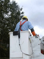
A lineman was thrown from a boom truck bucket near Madison, MN on April 24, 2026 while attempting to lift a traffic signal for an oversized load. He wasn’t wearing a fall protection harness or was it wasn’t hooked up.
What Happened
Near the intersection of US-75 and US-212 in Hamlin Township – roughly 5 miles south of Madison, Minnesota – a boom truck worker was attempting to lift a traffic signal mast arm to clear an oversized commercial load. The jib line snapped under the load, the boom whipped violently, and the worker was launched from the bucket.
He wasn’t wearing a fall protection harness or was it wasn’t hooked up. This happened in our service area – less than an hour from most of our job sites.
“Safety rules are written in blood. Every OSHA regulation exists because someone was hurt or killed doing exactly what the rule now prohibits.” – Common saying in the trades
What Went Wrong – Multiple Failures
This wasn’t a single mistake. It was a chain of failures:
- No fall protection harness. OSHA requires fall protection for any work above 6 feet. Bucket truck baskets have harness anchor points for exactly this scenario. The worker was unrestrained.
- Using a jib to lift a fixed structure. A jib crane is rated for discrete, free-hanging loads under 500 – 1,000 lbs. A traffic signal mast arm is steel bolted to a concrete foundation – the force increases with deflection, far exceeding jib capacity.
- Worker in the bucket during a high-load lift. The catapult effect – exactly what happened – is a known and documented hazard. The boom stores energy like a spring and releases it violently when the load breaks free.
- Route planning failure. The oversized load should never have reached this intersection without the clearance issue being addressed in advance.
What OSHA Requires for Aerial Lifts
- 29 CFR 1926.453(b)(2)(v) – Body harness and lanyard attached to the boom or basket at all times
- 29 CFR 1926.501(b)(1) – Fall protection required at 6 feet or more above a lower level
- Restraint lanyards recommended – Short enough to prevent ejection, not just arrest a fall after it
- Employer responsibility – Employer must provide equipment, ensure it’s worn, and train workers. Failure is an employer violation.
How We Handle Fall Protection at BHE
We do this kind of work. We work from bucket trucks, boom lifts, ladders, and rooftops. When we see an incident like this, we don’t think “that guy was careless.” We think: “that could be any of us on the wrong day with the wrong shortcut.” When operating high-voltage or complex installations, performing a thorough farm electrical safety audit is the first step to mapping utility lines and avoiding structural contact.
- Harness on before the bucket goes up. Every time. No exceptions. Even for “just a second.”
- Equipment inspected before every use. Harnesses, lanyards, and anchors checked for wear and damage each shift.
- No improvised lifting. If the equipment isn’t rated for it, we stop and get the right tool.
- Right to refuse unsafe work. Any crew member can refuse a task they believe is unsafe. The job is never more important than going home.
Fall Protection FAQ
Yes. OSHA standard 29 CFR 1926.453(b)(2)(v) requires workers in aerial lifts to wear a body harness with a lanyard attached to the boom or basket at all times. This applies to boom trucks, bucket trucks, cherry pickers, and all MEWPs.
The catapult effect occurs when a boom under tension is suddenly released, causing it to whip violently. This can happen when a boom snags on an obstruction, a jib line snaps, or a tire drops off a curb while extended. The force can eject an unrestrained worker at high velocity. A restraint lanyard is the primary defense.
Boom trucks with a jib crane can lift loads within rated capacity – typically 500 to 1,000 lbs. The jib is designed for free-hanging loads like transformers and crossarms, not fixed structures bolted to the ground. Lifting a fixed structure creates a spring-load that increases with deflection, quickly exceeding capacity.
Ask about fall protection policy and training. Look for documented training, inspected harnesses, a written safety program, and a culture where workers can refuse unsafe tasks. If you see a contractor working at height without fall protection, that tells you everything about their standards on work you can’t see.
Bright Haven Electric – Safety-First Electrical Work
Licensed, insured, and safety-trained electrical services across West Central Minnesota.
Need Electrical Work Done Right – and Safe?
No shortcuts. No improvisation. Just professional work from a crew that takes safety personally.
SPAN Panel Goes Open:
Local API, On-Premise Dashboard, and Eaton Partnership
What April 2026’s biggest smart panel announcements mean for Minnesota homeowners – from a certified SPAN installer who has been waiting for this.
Why This Is a Big Deal
Until now, smart electrical panels have been walled gardens. You buy the panel, your data goes to the manufacturer’s cloud, and you access it through their app. You can’t export it. You can’t integrate it. You can’t build on top of it. The panel is in your home, but the data lives on someone else’s server.
SPAN just changed that. In April 2026, they released three announcements that, together, represent the most significant shift in smart panel technology since the category was created:
SPAN API
A public, documented local API that lets homeowners access their panel data directly over their home network. No cloud. No middleman. Your panel, your data.
Public Beta – Available NowSPAN Home On-Premise
A browser-based local dashboard that works during power outages – no internet required. Monitor circuits, toggle loads, and manage backup priorities from any device on your network.
Works OfflineSPAN × Eaton
Eaton – one of the most trusted names in electrical distribution – now offers smart panels with SPAN Energy Intelligence inside. Same technology, broader availability.
More Options for Buyers“It only took me 5.5 years to make that happen!” – Don Jackson, SPAN, responding to the API release on social media (April 23, 2026)
When the person who built the feature says it took half a decade, you know it was a priority – and you know it was done right. This isn’t a rushed afterthought. It’s a deliberate architectural decision to give homeowners ownership of their energy data.
What the SPAN API Actually Does
The SPAN API is a local-only integration interface that runs directly on your SPAN Panel. It uses MQTT – the same lightweight messaging protocol used in industrial automation and smart home platforms – over your home’s local area network. No data leaves your house.
SPAN API – Technical Overview
What Can You Do With It?
The API opens up integrations that were previously impossible without reverse-engineering or unofficial workarounds:
- Home Assistant integration – monitor every circuit in your panel from your existing smart home dashboard. See which circuits are drawing power, set automations based on energy usage, and get alerts when loads exceed thresholds.
- Grafana dashboards – store historical energy data locally and build detailed charts showing consumption patterns over days, weeks, and months. Compare your solar production to grid consumption in real time.
- Custom automations – automatically shed non-essential loads during peak pricing windows. Turn off the EV charger when the dryer is running. Prioritize battery backup for critical circuits during outages.
- Per-circuit control – remotely toggle individual circuit relays through the API. Turn off the barn lights from your phone without a separate smart switch.
- Multi-system coordination – tie your SPAN Panel data into your solar inverter, battery system, and EV charger for unified energy management across your entire property.
A Note on Security and Privacy
The SPAN API runs entirely on your local network. Data never leaves your home unless you explicitly send it somewhere. Authentication is credential-based and locally controlled – the homeowner decides who gets access. This is a fundamentally different model from cloud-dependent smart home devices that phone home to a manufacturer’s server.
SPAN’s documentation follows open standards (eBus/Homie), which means the integration framework isn’t proprietary to SPAN. Other manufacturers can adopt the same protocol, creating a path toward real interoperability between smart electrical devices.
SPAN Home On-Premise: Your Panel, Offline
The second major announcement is SPAN Home On-premise – a browser-based dashboard that connects directly to your SPAN Panel over your local network. No internet. No cloud. No app store download. Just open a browser on any device connected to your home Wi-Fi.
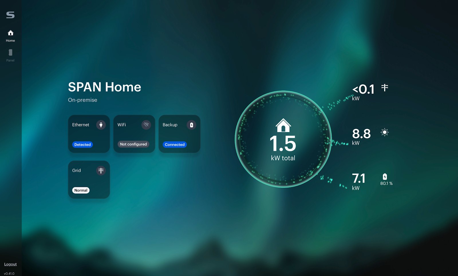
This matters enormously for rural Minnesota. During an extended power outage – the kind we get every winter – your internet goes down with the power. If you’ve battery backup, the SPAN Home On-premise app lets you:
- View overall panel status – grid connection, battery level, solar production at a glance
- Monitor circuit-level power usage – see exactly which circuits are drawing from your battery
- Turn circuits on and off – shed loads to extend battery life during a prolonged outage
- Adjust backup priorities – move circuits between “must stay on” and “shed if needed” categories in real time
Why This Matters for Rural MN
In West Central Minnesota, we regularly see winter storms that knock out power for 12 to 48 hours. Cell towers go down. Internet goes down. If your smart panel only works through a cloud app, you lose control of your home energy system at the exact moment you need it most.
SPAN Home On-premise solves this. If your panel has battery backup and your router is on a backed-up circuit, you’ve full local control of every circuit in your home – from your phone, tablet, or laptop – with zero internet dependency. This is how smart panels should work in rural areas.
SPAN × Eaton: What Changes for Buyers
The third announcement is a strategic collaboration between SPAN and Eaton – one of the most recognized names in electrical distribution. Eaton will now manufacture and distribute smart panels featuring SPAN Energy Intelligence™ technology through Eaton’s existing distribution channels.
Here is what that means in plain language:
More Options
You can install either an Eaton-branded or SPAN-branded smart panel and get the same core technology. Choose the model that works best for your home and your electrician’s preferred breaker line.
Wider Availability
Eaton’s distribution network means smart panels will be available at more electrical supply houses. Less lead time, more inventory, easier for your installer to source.
Same Installer Required
Both Eaton and SPAN-branded panels still require a SPAN Authorized Installer for commissioning. The smart features need proper configuration – this isn’t a DIY install.
Eaton Smart Panel Models
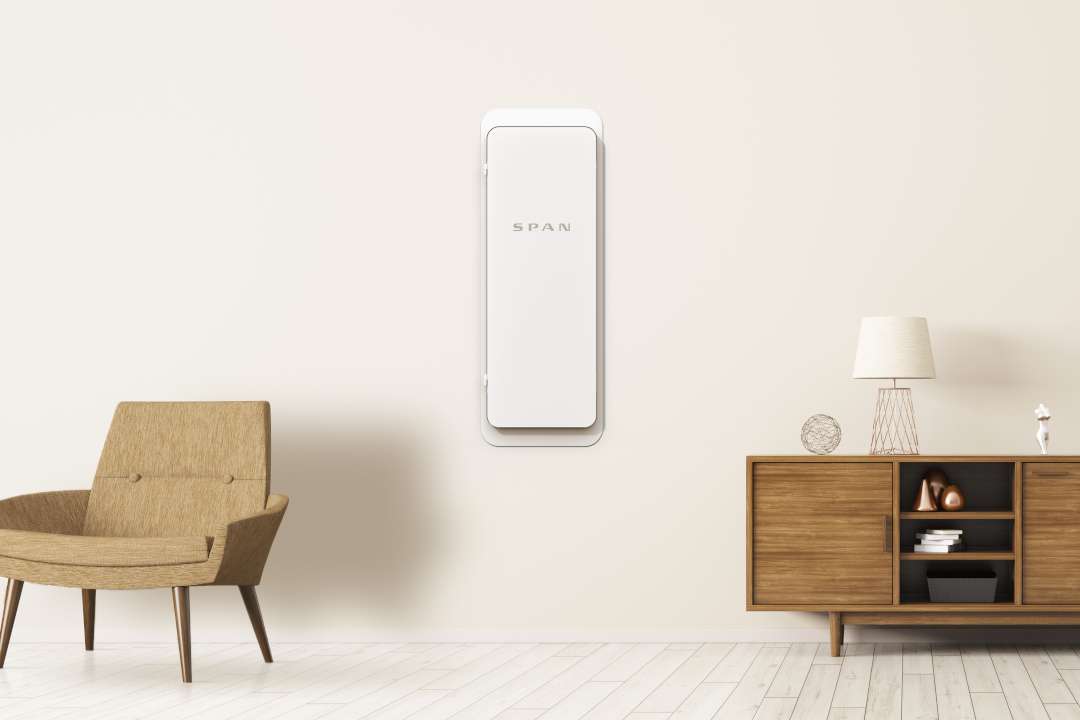
Eaton Smart Panels with SPAN Energy Intelligence will be available in MAIN 16, MLO 24, MAIN 40, and MLO 48 configurations through Eaton distribution channels. SPAN continues to manufacture its own line of panels independently. The SPAN Panel MAIN 32 – currently the only model with API support – remains a SPAN-branded product.
API support for Eaton’s models and SPAN’s additional models is expected in the second half of 2026.
Why We Are Watching This Closely
As a certified SPAN installer in West Central Minnesota, these announcements align with exactly what we’ve been asking for. Here is our perspective:
Local API access matters for rural homeowners. Most of our customers are on co-op power with variable rates, unreliable internet, and properties where a single panel might serve the house, the shop, and the barn. The ability to integrate a smart panel with Home Assistant or a local monitoring system – without depending on a cloud service – is a genuine upgrade in reliability.
The eBus/Homie framework is the right approach. SPAN didn’t invent a proprietary protocol. They adopted Electrification Bus (eBus), an open multi-vendor integration framework. That means when other manufacturers follow – and they’ll – the integrations you build today should work with tomorrow’s hardware.
Smart panels are no longer luxury items. With the Eaton partnership expanding distribution and the API giving homeowners real control over their data, smart panels are moving from “early adopter” territory into the mainstream. We expect demand to accelerate – especially for new construction and 200-amp service upgrades where you’re replacing the panel anyway.
Should You Get a Smart Panel?
A smart panel isn’t for everyone – yet. Here is a straightforward decision framework:
Strong Fit
- You’re building new or replacing a panel anyway – the incremental cost is lowest here
- You’ve solar, battery, or an EV charger and want unified monitoring of all three
- You run Home Assistant or another local smart home platform
- You want per-circuit control during outages with battery backup
- You’re on a co-op with variable or time-of-use rates and want to optimize consumption
Wait and See
- Your current panel is modern, safe, and has plenty of capacity
- You don’t have solar, battery, or EV charging (the ROI is lower without these)
- You want API access but don’t have a MAIN 32 – other models get API support in H2 2026
- Budget is the primary constraint – a standard panel upgrade at $2,500-$5,500 may be the better investment right now
What Does a SPAN Panel Cost in 2026?
An installed SPAN smart panel typically costs between $6,500 and $10,000+ in 2026, including the panel itself ($3,000-$5,500) and professional installation ($2,000-$6,000+). The final price depends on your electrical configuration – whether it’s a main panel upgrade, a subpanel installation, and how much existing work needs to be updated to accommodate the smart panel.
For context, a standard 200-amp panel replacement in West Central Minnesota typically runs $2,500-$5,500. The smart panel premium – roughly $3,000-$5,000 – gets you per-circuit monitoring, remote control, smart load management, and now an open API for custom integrations. For homes with solar, battery, or EV charging, the payback through energy optimization can be significant.
Smart Panel FAQ
Common questions about the SPAN Panel, the new API, and smart panel installations in Minnesota.
The SPAN Panel API is a local, LAN-based interface that lets homeowners and developers access their SPAN Panel data directly over their home network. It uses MQTT (a lightweight messaging protocol) following the Electrification Bus (eBus) framework. You can use it to integrate your panel with home automation platforms like Home Assistant, build custom energy dashboards with tools like Grafana, and automate load management based on real-time energy data. The API is currently available on the SPAN Panel MAIN 32 with firmware r202603 or later. It’s provided for personal, non-commercial use only.
Yes. The core SPAN Panel functions – circuit-level monitoring, relay control, and load management – operate independently of internet connectivity. The new SPAN Home On-premise app takes this further by providing a full browser-based dashboard that runs entirely on your local network. During a power outage with battery backup, you can monitor circuits, toggle loads, and adjust backup priorities from any device on your home Wi-Fi – even with zero internet access. This is especially valuable in rural Minnesota where internet outages often coincide with power outages.
Yes. The SPAN API was designed with home automation integration in mind. Because it uses MQTT – the same protocol Home Assistant already supports natively – you can subscribe to your panel’s circuit-level data, create automations based on energy usage, and control individual circuits from your Home Assistant dashboard. Community-maintained integrations are available through HACS (Home Assistant Community Store). The official API documentation and example code are published on GitHub.
Eaton smart panels use SPAN Energy Intelligence technology inside – the same core software and capabilities as SPAN-branded panels. The difference is branding, distribution, and breaker compatibility. Eaton panels are available through Eaton’s distribution channels in MAIN 16, MLO 24, MAIN 40, and MLO 48 models. SPAN continues to manufacture its own line, including the SPAN Panel MAIN 32 which currently has API support. Both require a SPAN Authorized Installer for commissioning. Choose based on your electrician’s preferred breaker line and local availability.
A fully installed SPAN smart panel in Minnesota typically costs between $6,500 and $10,000+ in 2026. This includes the panel ($3,000-$5,500) and professional installation ($2,000-$6,000+). The total depends on whether you’re doing a main panel upgrade or subpanel installation, the condition of your existing wiring, and whether additional work like a service entrance upgrade is required. For comparison, a standard 200-amp panel replacement typically costs $2,500-$5,500. The smart panel premium is roughly $3,000-$5,000 for per-circuit monitoring, remote control, and smart load management.
Yes. SPAN Panels – and Eaton Smart Panels with SPAN Energy Intelligence – must be commissioned by a SPAN Authorized Installer. This isn’t just a marketing designation. The commissioning process involves configuring each circuit in the panel’s software, setting up monitoring parameters, calibrating current transformers, and verifying relay operation. A standard electrician can do the physical installation, but the smart panel commissioning requires SPAN-specific training and the SPAN Installer App. Bright Haven Electric is a certified SPAN installer serving West Central Minnesota.
Bright Haven Electric – SPAN Certified Installer
We install and commission SPAN Panels across West Central Minnesota. Whether you’re building new, replacing a dangerous panel, or upgrading to add solar and battery storage, we can help you evaluate whether a smart panel makes sense for your situation.
Ready to Upgrade to a Smart Panel?
Get a transparent quote for a SPAN Panel installation – including commissioning, configuration, and a walkthrough of the API and local dashboard features.
Is Your Electrical Panel Dangerous?
7 warning signs Minnesota homeowners miss – including recalled brands still installed in thousands of homes across West Central MN. If your panel is over 25 years old, read this before it makes the decision for you.
Your electrical panel is the most critical safety device in your home. Every circuit, every outlet, every appliance runs through it. When it works correctly, you never think about it. When it fails, the consequences range from nuisance breaker trips to a house fire that starts inside your walls while you sleep.
The problem is that dangerous electrical panels don’t announce themselves. They don’t beep. They don’t flash a warning light. They degrade silently – corroding connections, weakening breaker mechanisms, building heat at failing contact points – until the day they can’t interrupt a fault and the wiring behind your drywall ignites. By the time you smell smoke, the fire has a head start.
Thousands of Minnesota homes – including homes across our West Central Minnesota service area – still have panels that were recalled, panels with known failure rates, and panels so old that replacement parts no longer exist. Many homeowners have no idea. This guide will help you identify the 7 warning signs of a dangerous electrical panel, recognize recalled brands by name, and understand what a professional inspection actually checks. If any of this applies to your home, don’t wait.
The 7 Warning Signs of a Dangerous Electrical Panel
Most homeowners walk past their electrical panel every day without looking at it. That’s exactly how these problems go undetected for years. Here are the seven signs that your panel may be a fire hazard – any single one of these warrants a professional electrical panel inspection:
1. Burning Smell or Scorch Marks
A burning smell near your electrical panel is never normal. It means something is overheating – a loose connection, a failing breaker, or insulation breaking down under excessive heat. Scorch marks, discoloration, or melted plastic on or around the panel confirm that arcing or thermal damage has already occurred. This isn’t a “watch it and see” situation. Turn off the main breaker if safe to do so and call a licensed electrician immediately.
Immediate Fire Risk2. Breakers That Trip Repeatedly
A breaker that trips once is doing its job. A breaker that trips repeatedly on the same circuit is telling you something is wrong – either the circuit is overloaded, there’s a short circuit or ground fault downstream, or the breaker itself is failing. Worn breakers lose their ability to trip at the correct current threshold. They may trip too easily, or worse, they may stop tripping at all – which means they won’t protect you from a fault that could start a fire.
Breaker Failure Risk3. Buzzing, Crackling, or Humming Sounds
Electrical panels should be silent. If you hear buzzing, crackling, sizzling, or humming coming from your panel, an active electrical fault is occurring inside the enclosure. Buzzing typically indicates a loose connection or a breaker that’s arcing internally. Crackling or sizzling means arcing is occurring at a connection point – this generates extreme heat at the arc site and can ignite surrounding materials. Don’t ignore electrical sounds from your panel.
Active Arcing Hazard4. Rust, Moisture, or Corrosion Inside
Open your panel door and look inside. Rust on bus bars, corrosion on breaker terminals, green patina on copper conductors, or any evidence of moisture means water has entered the enclosure. Water and electricity inside a panel create corrosion that degrades connections over time, increasing resistance and generating heat. In severe cases, moisture on energized bus bars causes tracking – a carbonized path that conducts current along the surface and can ignite.
Corrosion Degrades Protection5. Warm or Hot Breakers and Wiring
Touch the front of your breaker handles (with dry hands, panel door open). Breakers should be cool or barely warm. A breaker that feels noticeably warm or hot is either overloaded or has a failing internal connection. Hot wiring at the panel – especially at the bus bar connections – indicates a loose lug, undersized conductor, or high-resistance joint. These hot spots are where fires begin. An infrared inspection can detect hot spots invisible to the naked eye.
Thermal Failure Point6. Flickering or Dimming Lights
Lights that flicker or dim when appliances turn on may indicate a panel problem – not just a wiring issue. If the flickering is widespread (multiple rooms, multiple circuits), the issue is likely at the panel: a loose main lug connection, a deteriorating bus bar, or a failing main breaker. Loose connections at the panel create intermittent contact, causing voltage fluctuations throughout the house. This is also a leading symptom of aluminum wiring connections that have oxidized.
Loose Connection Indicator7. Panel Is 25+ Years Old or a Recalled Brand
Age alone is a risk factor. Breaker mechanisms wear out. Internal connections loosen from decades of thermal cycling. Insulation materials degrade. A panel installed in the 1980s or earlier has exceeded its expected service life. If your panel carries a brand name from the recalled list below – Federal Pacific, Zinsco, Pushmatic – the risk isn’t theoretical. These panels have documented failure rates that have caused fires. If your home still has screw-shell fuses instead of circuit breakers, the panel predates modern safety standards entirely.
Replace – Do Not Repair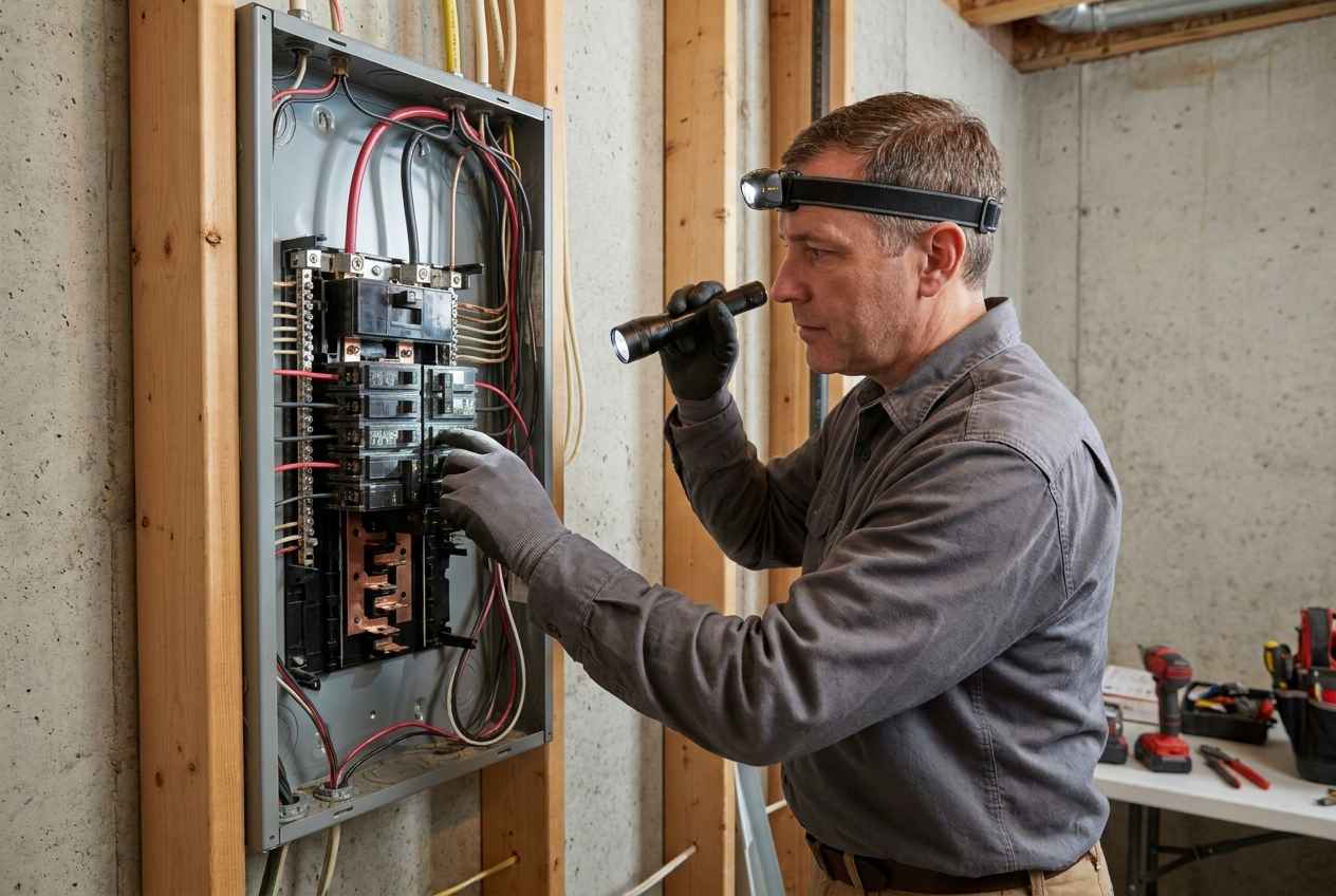
Recalled & Dangerous Panel Brands Still in Minnesota Homes
Not all electrical panels are created equal. Several panel brands manufactured from the 1950s through the 1990s have documented histories of breaker failure, fire, and recall. These panels are no longer manufactured – but they’re still installed in thousands of homes across Minnesota, including many in our West Central MN service area. If your panel carries any of these brand names, replacement is the only safe option.
Federal Pacific Electric (FPE) Stab-Lok
Federal Pacific Stab-Lok panels are the most widely documented dangerous panel in U.S. residential history. Independent testing has shown that FPE Stab-Lok breakers fail to trip in up to 25 – 30% of overload conditions. The breakers don’t reliably interrupt fault current – they allow the circuit to remain energized during a short circuit or overload, which causes the wiring to overheat and ignite. FPE panels were installed in millions of homes from the 1950s through the 1980s and are extremely common in West Central Minnesota. There’s no repair. The panel must be replaced.
Most Common – Replace ImmediatelyZinsco / GTE-Sylvania
Zinsco panels (later sold under the GTE-Sylvania and Sylvania brand names) suffer from a design flaw where the breakers fuse to the bus bar. When a breaker welds itself to the bus, it can’t trip – it’s physically locked in the ON position. The breaker handle may appear to be OFF while the circuit remains energized. These panels also have aluminum bus bars that corrode and create high-resistance connections. Zinsco panels were installed from the 1970s through the early 1990s. No retrofit or repair can fix the underlying design defect.
Breakers Fuse to Bus BarPushmatic (ITE / Bulldog)
Pushmatic panels use push-button breakers instead of toggle switches. These breakers are no longer manufactured, and replacement breakers are either unavailable or unreliable aftermarket units. The push-button mechanism wears out over time, and the breakers lose the ability to trip reliably. Because parts are unavailable, an electrician can’t properly maintain or repair these panels. If a breaker fails, the only option is full panel replacement. Adding circuits is impossible – no modern breakers fit the bus.
Parts UnavailableChallenger (CPSC Recalled)
The U.S. Consumer Product Safety Commission (CPSC) recalled certain Challenger panel models due to breakers that fail to trip during overcurrent conditions. Challenger panels were widely installed in new construction from the 1980s through the late 1990s. The affected breakers – particularly the HAGB and GFI models – can allow sustained overcurrent that overheats wiring. If your home was built in the 1980s or 1990s, check the panel door label for the Challenger brand name. Some recalled units were also sold under the Westinghouse and Cutler-Hammer brands.
CPSC RecallScrew-Shell Fuse Panels
If your home still has a fuse box instead of a circuit breaker panel – with screw-in glass or ceramic fuses – the entire system predates modern electrical safety standards. Fuse panels have no AFCI or GFCI protection capability. They can’t accommodate the electrical loads of modern homes (air conditioning, EV chargers, electric appliances). Homeowners frequently install oversized fuses to stop blowing them – which defeats the overcurrent protection entirely and allows wiring to overheat. Screw-shell fuse panels are very common in older homes across rural Minnesota and are a frequent cause of insurance policy cancellations.
Predates Modern Safety StandardsHow to Check Your Panel Brand
- Open the panel door – the brand name is typically printed on the inside of the door, on a label on the panel cover, or stamped into the metal enclosure
- Look at the breakers – the brand name is molded into the breaker handle or printed on the breaker face. FPE Stab-Lok breakers have the Stab-Lok name on every unit
- If the panel has glass or ceramic fuses that screw in – you’ve a fuse panel that needs to be upgraded to a modern breaker panel
- If you can’t identify the brand – take a clear photo of the panel with the door open and send it to us. We’ll identify it for you at no charge
- Don’t remove the panel cover (dead front) – the panel cover is the inner metal plate that covers the bus bars and wiring. Only a licensed electrician should remove it. Lethal voltages are exposed behind the cover
“I have pulled Federal Pacific panels out of homes where the breakers were visibly melted to the bus bar. The homeowner had been living with that for years – never knew. Every FPE Stab-Lok panel I open, I find breakers that won’t trip under test. Not some of them. Every single one. That’s why we tell homeowners: there’s no repair for these panels. Replacement is the only answer.” – Chadwick Ferguson, Master Electrician & Co-Owner, Bright Haven Electric LLC
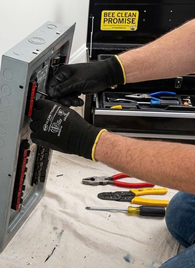
What a Professional Panel Inspection Checks
A panel inspection isn’t just opening the door and looking inside. A properly trained electrician evaluates the entire service entrance and distribution system. Here is what our electrical safety audit covers when we inspect a panel:
Time needed: 1 hour and 30 minutes
A professional electrical panel inspection evaluates the entire service entrance and distribution system for safety hazards, code violations, and equipment failures. This is the process Bright Haven Electric follows on every residential panel inspection in West Central Minnesota. This inspection must be performed by a licensed electrician. Homeowners shouldn’t remove the panel dead front or test breakers on recalled panels.
- Identify the panel manufacturer, model, and age
Verify the brand name on the panel door, enclosure, and breaker handles against known recall and failure databases. If the panel is a recalled brand (Federal Pacific, Zinsco, Challenger), recommend full replacement regardless of the panel’s current visual condition. Document the panel model number, amperage rating, and estimated installation date.
- Inspect the service entrance and meter base
Check the weatherhead, service mast, meter socket, and main disconnect for physical damage, corrosion, and code compliance. Verify that the service entrance cable is properly secured, the drip loops are intact, and the meter enclosure seal isn’t compromised. A damaged service entrance affects the entire system downstream.
- Remove the dead front and inspect bus bars, lugs, and connections
With the dead front removed, inspect every conductor termination for discoloration, heat damage, corrosion, melted insulation, and loose connections. Check the main lugs and bus bar for signs of arcing or overheating. This is where most hidden hazards are found – problems invisible from outside the panel.
- Test every breaker for proper operation
Toggle each breaker OFF and back ON. Check for breakers that are difficult to reset, feel loose in the bus, or show signs of internal damage such as discoloration or a burnt smell. Breakers that don’t seat firmly into the bus are a fire hazard. On non-recalled panels, perform trip testing on sample breakers to verify the trip mechanism functions correctly.
- Verify circuit labeling and load distribution
Mislabeled or unlabeled panels are a safety issue – no one can safely isolate a circuit in an emergency if the labels are wrong. Verify and correct the panel schedule. Check load balance across phases and identify any circuits that are overloaded or sharing neutrals improperly.
- Check grounding and bonding
Verify that the grounding electrode conductor is properly connected to the grounding electrode system, that the main bonding jumper is installed correctly, and that the neutral and ground bus bars are configured properly for the panel type (main panel vs. sub-panel). Improper grounding is one of the most dangerous and most common deficiencies.
- Evaluate AFCI and GFCI protection
Current NEC code requires AFCI and GFCI protection on most residential circuits – bedrooms, kitchens, bathrooms, laundry, garages, basements, and outdoors. Document which circuits lack required protection and recommend upgrades. Test all existing AFCI and GFCI breakers for proper trip function.
- Assess panel capacity for current and future loads
If you’re planning an EV charger, hot tub, shop, or other high-draw addition, evaluate whether the panel has sufficient amperage and available breaker spaces – or whether a 200-amp service upgrade is needed. Document available capacity and provide recommendations for future electrical planning.
Insurance, Home Sales, and Panel Replacement
Your electrical panel isn’t just a safety issue – it’s a financial one. Insurance companies, home inspectors, and real estate transactions all converge on the electrical panel. Here is what homeowners across Minnesota need to understand:
Insurance Cancellation
Insurance companies are denying coverage and cancelling policies on homes with Federal Pacific, Zinsco, and fuse panels at increasing rates. If you receive an insurance cancellation notice citing your electrical panel, you typically have 30 – 60 days to replace the panel and provide documentation. We provide the inspection, replacement, and compliance letter your insurer requires – on a timeline that protects your coverage.
30 – 60 Day DeadlineHome Sales and Inspections
A dangerous or recalled electrical panel will appear on every competent home inspection report. It can delay or kill a sale. Buyers’ lenders may refuse to finance a home with a recalled panel. Sellers who replace the panel before listing eliminate a major negotiation point and demonstrate that the home has been properly maintained. We work with homeowners, realtors, and home inspectors to resolve panel issues before they become deal-breakers.
Pre-Listing AdvantagePanel Upgrade Benefits
A modern 200-amp panel does more than eliminate fire risk. It provides room for EV chargers, heat pumps, electric ranges, and other modern loads. It includes AFCI breakers that detect arc faults – a leading cause of electrical fires. It gives you a properly labeled, properly grounded electrical system that meets current NEC code. And it gives you confidence in your electrical system that the most critical safety device in your home actually works.
Modern ProtectionWhat Does a Panel Replacement Cost?
Panel replacement costs vary based on the existing installation, panel size, and any additional work required (service entrance repair, grounding system upgrades, circuit rewiring). In our service area, a typical residential panel replacement ranges from $2,500 to $5,500 for a standard 200-amp upgrade. This includes the new panel, breakers, labor, permit, and inspection.
Some electric cooperatives offer rebates for panel and service upgrades. We help homeowners identify available rebates and incentives. We also provide transparent, itemized quotes before any work begins – no surprises, no hidden fees.
If your panel is a recalled brand or has any of the warning signs listed above, the cost of replacement is a fraction of the cost of an electrical fire. Insurance deductibles, temporary housing, personal property loss, and rebuilding costs dwarf the price of a panel. The math is simple.
Panel Inspections Across West Central Minnesota
Bright Haven Electric LLC is a Class A electrical contractor serving residential, commercial, and industrial customers across West Central Minnesota. We’ve inspected and replaced panels in homes dating from the 1920s to the 2020s – from farmsteads with original fuse panels to lake homes with Federal Pacific Stab-Lok installations.
We serve homeowners throughout our 10-county service area including:
Not sure what panel you’ve? Send us a photo. We’ll identify the manufacturer, check it against recall databases, and let you know whether an inspection is warranted. No charge for the identification – we would rather catch a dangerous panel before it catches fire.
Electrical Panel Safety FAQ
Below are the most common questions we receive about electrical panel safety, recalled brands, and panel replacement in Minnesota.
Look for the 7 warning signs: burning smell or scorch marks, breakers that trip repeatedly, buzzing or crackling sounds, rust or moisture inside the panel, warm or hot breakers, flickering lights, and a panel that’s over 25 years old or a recalled brand. Open your panel door and check the brand name on the inside of the door or on the breaker handles. If you see Federal Pacific, Stab-Lok, Zinsco, GTE-Sylvania, Pushmatic, or Challenger – or if your panel uses screw-in fuses instead of circuit breakers – contact a licensed electrician for an inspection. Any single warning sign warrants professional evaluation.
Yes. Independent testing has shown that Federal Pacific Stab-Lok breakers fail to trip during overcurrent events in up to 25 – 30% of tests. When a breaker doesn’t trip, the circuit remains energized during a short circuit or overload, allowing wiring to overheat and potentially ignite. FPE panels were never formally recalled by the CPSC, but every major electrical safety organization and home inspection association recommends replacement. FPE panels are extremely common in homes built from the 1950s through the 1980s across Minnesota. There’s no retrofit or repair – full panel replacement is the only solution.
Insurance companies are increasingly denying coverage and cancelling policies on homes with Federal Pacific, Zinsco, and fuse panels. If your insurer identifies a recalled or outdated panel during an inspection or policy review, you may receive a cancellation notice with a 30 – 60 day deadline to remedy the issue. Bright Haven Electric provides the panel replacement and written compliance documentation your insurer requires. We work within insurance deadlines to protect your coverage.
A typical residential panel replacement in West Central Minnesota ranges from $2,500 to $5,500 for a standard 200-amp upgrade. The cost depends on the existing installation condition, panel size, whether the service entrance needs repair, and whether additional work like grounding system upgrades or AFCI breaker installation is required. This includes the new panel, all breakers, labor, electrical permit, and inspection. Some electric cooperative rebates may offset part of the cost. We provide transparent, itemized quotes before any work begins.
No. For Federal Pacific, Zinsco, and Pushmatic panels, the failure is a design defect in the panel and breaker system – not a problem with individual breakers. Replacement breakers for these panels are either unavailable, aftermarket units of questionable quality, or from the same defective product line. Installing new breakers in a panel with a defective bus bar doesn’t fix the bus bar. The only safe remediation is full panel replacement with a modern, UL-listed panel and breakers from a current manufacturer.
Fuse panels aren’t inherently dangerous when properly maintained and correctly fused – but they’re obsolete. They can’t accommodate AFCI or GFCI protection, they’re limited in capacity for modern electrical loads, and replacement fuses are increasingly difficult to find. The most common danger is homeowners installing oversized fuses to prevent nuisance blowing – a 30-amp fuse on a 15-amp circuit defeats all overcurrent protection and allows wiring to overheat. Fuse panels are also a common reason for insurance policy cancellations in Minnesota. We recommend upgrading fuse panels to modern breaker panels for safety, capacity, and insurability.
Don’t ignore it. A burning smell from your electrical panel means something is overheating – a failing breaker, a loose connection, or degrading insulation. If you can safely reach the main breaker, turn it off. Don’t touch any breaker that appears damaged, discolored, or melted. Call a licensed electrician immediately. Don’t reset the main breaker until a professional has inspected the panel. If you see smoke or flames, leave the home and call 911. Electrical panel fires can spread into wall cavities very quickly.
Possibly. A Level 2 EV charger typically requires a 40 – 60 amp dedicated circuit. A hot tub requires a 40 – 50 amp circuit. If your existing panel is at or near capacity, doesn’t have available breaker spaces, or is an older 100-amp service, you’ll likely need a 200-amp service upgrade before adding these loads. We assess panel capacity as part of every EV charger and hot tub installation quote. Planning the panel upgrade alongside the new load is the most cost-effective approach.
Related Safety Guides
- Home Electrical Safety Inspection – Our full 72-point inspection covers your panel, wiring, grounding, and every outlet in the house
- Electrical Shock Prevention Guide – Dangerous panels increase shock risk. Learn how to protect your family from electrocution hazards
Bright Haven Electric – Safety-First Electrical Work
Licensed, insured, and safety-trained electrical services across West Central Minnesota.
Is Your Panel Safe? Find Out Now.
Don’t wait for a fire to tell you your panel was dangerous. A professional inspection takes under 90 minutes and gives you a definitive answer – along with a written report and clear next steps.
Dock Electrical Safety & ESD Prevention
Electric shock drowning is invisible and fatal. Every Minnesota lake property owner needs to understand dock electrical hazards – and how to eliminate them before swim season.
Every summer, swimmers and boaters die in fresh water from a hazard they never saw. No warning. No visible sign. The water around a dock, marina, or boat lift carries an electrical current from a wiring fault – and anyone who enters that water is paralyzed by the shock before they can call for help. It’s called electric shock drowning (ESD), and it’s one of the most preventable causes of death in lake country.
Dock electrical safety isn’t optional. It isn’t something you check “when you get around to it.” Every dock, boat lift, shore power pedestal, and underwater light on your property is a potential source of lethal current – if the wiring isn’t installed correctly, protected by working GFCI devices, and inspected regularly. The National Electrical Code (NEC Articles 555, 680, and 682) exists specifically because people have died.
This guide covers how dock electrical faults happen, what electric shock drowning looks like from shore, the code-required protections every Minnesota dock installation must have, and the annual inspection you should schedule before anyone enters the water. We serve lake property owners across West Central Minnesota’s Big Stone Lake, Lac qui Parle Lake, Pomme de Terre Lake, Lake Minnewaska, and dozens of other bodies of water in our 10-county service area.
What Is Electric Shock Drowning?
Electric shock drowning occurs when AC electrical current leaks into the water surrounding a dock, marina, boat lift, or moored vessel. The current enters the water through a ground fault – a wiring defect that allows electricity to follow an unintended path. In fresh water, that unintended path runs through anyone in the water.
Fresh water is a poor conductor compared to the human body. When current leaks into fresh water, it preferentially flows through the body of a swimmer because the human body offers a lower-resistance path. The electrical current causes involuntary muscle contraction – the swimmer can’t move, can’t call for help, and drowns while still conscious. From the surface, it looks like a drowning. Rescuers who jump in to help are exposed to the same current.
The Mechanism
AC current as low as 10 milliamps can cause loss of muscle control in water. The swimmer can’t coordinate their limbs. They can’t keep their head above the surface. Even a strong swimmer is helpless – the current overrides voluntary muscle control. It takes just 100 milliamps across the heart to cause ventricular fibrillation. A single circuit with a ground fault can leak far more than that into the water surrounding a dock.
Lethal Below 100mAWhy It Is Invisible
There’s no visual cue. The water doesn’t bubble, change color, or look different. Voltage gradients in the water are undetectable without instrumentation. A swimmer enters the field, loses muscle control, and sinks. Witnesses see a person struggling and assume it’s a standard drowning. Many ESD deaths are classified as accidental drowning because the electrical cause is never investigated.
No Visible WarningWho Is at Risk
Anyone in the water near energized dock infrastructure. Children are particularly vulnerable because they swim closer to docks, ladders, and boat lifts – the areas where voltage gradients are strongest. Rescuers who jump in to help a struggling swimmer are exposed to the same current. Pets that swim near docks are equally at risk. The hazard zone extends up to 50 feet from a fault source in fresh water.
50-Foot Hazard ZoneFresh Water vs. Salt Water
Salt water is a far better conductor than the human body, so current in salt water flows through the water rather than through a swimmer. Fresh water – the water in every Minnesota lake – is a worse conductor than the body. Current in fresh water takes the path of least resistance: directly through anyone in it. This is why ESD is overwhelmingly a fresh water phenomenon, and why Minnesota’s lake country faces this risk specifically.
Fresh Water = Higher Risk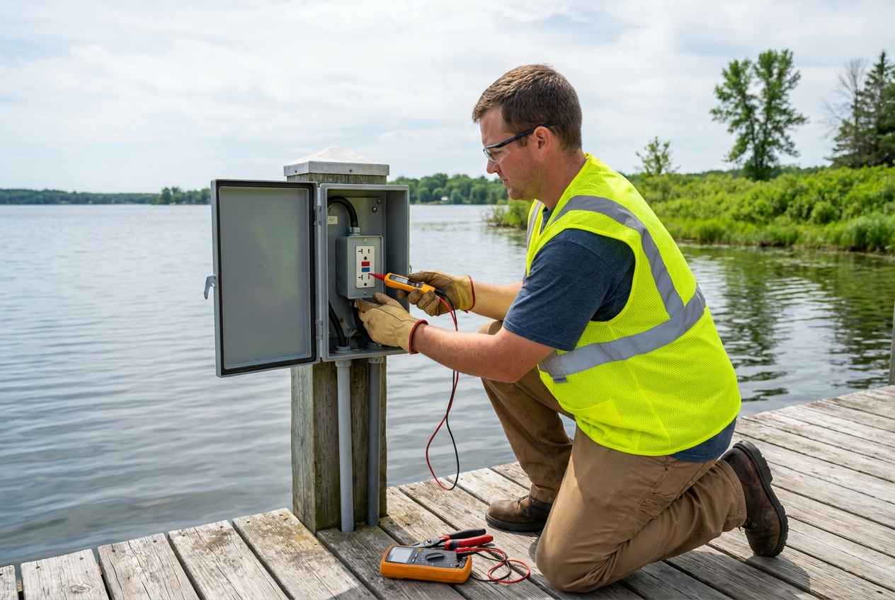
How Dock Electrical Faults Happen
Dock electrical systems operate in the harshest environment your property has – constant moisture, UV exposure, ice loading, wave action, and physical abuse from boats and equipment. Every component degrades faster than its land-based equivalent. Here are the most common fault sources we find during dock inspections in West Central Minnesota:
Damaged Wiring and Connections
UV-degraded cable jackets, corroded terminals, and loose connections in junction boxes are the most frequent fault sources. Ice heaving shifts dock posts, stressing conduit and pulling wires. Boats strike shore power pedestals. Extension cords – which are never code-compliant for permanent dock power – abrade against metal edges and develop conductor exposure. Any exposed conductor near water creates a direct leakage path into the lake.
Most Common FaultBoat and Lift Motor Faults
Submersible boat lift motors, bilge pumps, and shore power connections on vessels can develop insulation failures that leak current into the water through the hull or lift frame. A boat plugged into shore power with a failing hot-water heater element or pump motor can energize the water around the entire dock. The fault may originate on a neighbor’s boat – you can’t control every vessel at a shared dock.
Vessel-Sourced FaultUnderwater and Landscape Lighting
Underwater dock lights, underwater fishing lights, and shoreline landscape lighting operate submerged or at the waterline. Any enclosure failure, seal leak, or conductor breach puts voltage directly into the water at the precise location where people swim. Low-voltage LED lighting is safer but not risk-free – a failed transformer or improperly grounded system still presents a shock hazard.
Direct Water ContactFailed or Missing GFCI Protection
A GFCI (ground fault circuit interrupter) detects current leakage as low as 4 – 6 milliamps and trips the circuit in milliseconds. Without working GFCI protection, a ground fault on any dock circuit leaks current into the water indefinitely. GFCIs fail – especially in outdoor environments. A GFCI that doesn’t trip when you press the TEST button has failed. Every dock circuit requires GFCI protection, and every GFCI must be tested regularly.
Last Line of DefenseIf You Suspect Electrical Current in the Water
- Do NOT enter the water – if a swimmer appears to be struggling near a dock or marina without an obvious cause, don’t jump in. You’ll be exposed to the same current
- Turn off all dock power immediately – find the breaker panel and shut off every circuit that feeds the dock, lift, and shoreline
- Throw a flotation device – use a life ring, rope, or any non-conductive thrown object to reach the victim without entering the water
- Call 911 – report a suspected electric shock drowning so responders bring the right equipment and approach
- Don’t touch metal on the dock – metal rails, ladders, and dock frames may be energized if a ground fault is present
“I have seen docks wired with extension cords, indoor-rated wire, and outlets held together with electrical tape – all within arm’s reach of the water. Every one of those installations is a potential fatality waiting for a swimmer to walk down the dock on a wet day. Dock electrical work isn’t a DIY project. The consequences of getting it wrong aren’t a tripped breaker – they’re a funeral.” – Chadwick Ferguson, Master Electrician & Co-Owner, Bright Haven Electric LLC
NEC Requirements for Dock Electrical Safety
The National Electrical Code dedicates entire articles to electrical installations near water because the stakes are life and death. If your dock, boat lift, or shoreline power was installed without following these requirements, it isn’t merely “not up to code” – it’s a lethal hazard. Here are the key NEC provisions that govern dock electrical installations:
Key NEC Articles for Dock and Marina Electrical Systems
- NEC Article 555 – Marinas, Boatyards, and Commercial/Noncommercial Docking Facilities: Requires GFCI protection for all 15A and 20A, 125V receptacles. Requires ground fault protection for 30A and 50A shore power outlets. Specifies wiring methods, receptacle enclosure ratings, and equipment grounding conductor requirements for all dock circuits.
- NEC Article 680 – Swimming Pools, Fountains, and Similar Installations: Covers any body of water with electrical equipment – including dock areas with underwater lighting. Requires equipotential bonding of all metal within specified distances of the water’s edge.
- NEC Article 682 – Natural and Artificially Made Bodies of Water: Added specifically for lakes, ponds, and rivers. Requires GFCI protection for all electrical equipment used in, on, or within specified distances of the water. Addresses boat hoists, dock electrical supply, and waterside lighting installations.
- GFCI Protection Is Non-Negotiable: Every receptacle on a dock, every shore power outlet, every circuit feeding a boat lift motor, and every underwater or near-water lighting circuit must be GFCI-protected. The 2023 NEC expanded GFCI requirements even further. If your dock installation predates current code, it likely needs upgrades.
- Equipotential Bonding: All metal parts of the dock structure, boat lift, dock ladders, and shore power pedestals within the required distance of the water must be bonded together and connected to the equipment grounding conductor. This bonding equalizes voltage potential between metal surfaces so a person touching two different objects isn’t exposed to a voltage difference.
Annual Dock Electrical Inspection – What We Check
Every dock electrical system should be professionally inspected before swim season. Winter’s freeze-thaw, ice loading, and spring storms degrade dock wiring faster than any other installation on your property. This is the inspection our team performs on lakeshore and waterfront properties across our service area:
Dock Electrical Inspection Checklist
Pre-Season Dock Inspection Items
- Test all GFCI devices. Press TEST on every GFCI outlet and GFCI breaker that protects dock circuits. Verify each device trips and resets. Replace any GFCI that fails to trip – it has zero protective value.
- Inspect all wiring, conduit, and junction boxes. Walk every run of conduit and cable. Check for UV degradation, physical damage, loose fittings, and corrosion. Open all accessible junction boxes and inspect for moisture intrusion, corroded terminals, and rodent damage.
- Verify equipotential bonding. Confirm all metal components – dock frame, boat lift, ladders, rails, and pedestal enclosures – are bonded together and connected to the equipment grounding conductor. Test bonding connections for continuity and tightness.
- Inspect shore power pedestals and receptacles. Open every pedestal and outlet enclosure. Check for corrosion, water intrusion, heat damage, and loose connections. Verify weatherproof covers are intact and operational. Confirm receptacle ratings match the installed circuits.
- Test boat lift motor circuits. Inspect wiring to submersible and above-dock lift motors. Check disconnect switches, motor overload protection, and ground fault protection. Verify the motor is properly grounded through the frame bonding system.
- Inspect underwater and shoreline lighting. Check all underwater light fixtures for seal integrity, enclosure cracks, and wiring damage. Verify low-voltage transformer grounding. Inspect landscape lighting conduit and connections at the waterline where wave action causes the most damage.
- Measure voltage in the water (if instrumentation is available). Using a calibrated voltage tester with waterproof probes, measure voltage gradients in the water around the dock and lift with all circuits energized. Any measurable voltage in the water indicates a fault that must be located and repaired immediately.
- Document and recommend. Record the inspection findings, photograph any deficiencies, and provide a written report with repair recommendations and code compliance status.
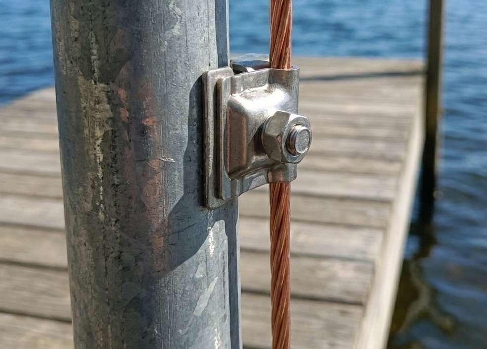
Why Dock Electrical Work Is Not a DIY Project
We understand the impulse. You wire your own outlets in the garage. You installed a ceiling fan. You ran an extension cord from the cabin to the dock “just for the weekend.” But dock electrical work is fundamentally different from any other residential wiring project – and the margin for error is zero.
The Difference Between Indoor Wiring and Dock Wiring
Inside your home, a wiring mistake might trip a breaker, blow a fuse, or create a localized shock hazard. On a dock, a wiring mistake puts lethal current into the water – an environment where people swim, children play, and pets drink. There’s no second chance.
- Extension cords are never acceptable for permanent dock power – they degrade in UV, abrade against metal, and aren’t rated for wet locations. NEC prohibits their use as a substitute for permanent wiring.
- Indoor-rated wire and devices will fail outdoors – standard NM-B (Romex) cable, indoor outlets, and non-weatherproof junction boxes deteriorate within one season of dock exposure.
- Improper grounding kills – a dock circuit without proper equipment grounding and bonding sends fault current directly into the water. This is the primary mechanism of electric shock drowning.
- Permits exist to protect you – Minnesota requires electrical permits for dock wiring. The inspection process catches errors before they endanger anyone. Unpermitted dock work puts your family and your neighbors at risk.
Dock Electrical Systems We Install and Service
Bright Haven Electric designs and installs dock electrical systems that comply with current NEC requirements and are built to withstand Minnesota’s lake environment. If you need a new power pedestal, a boat lift circuit, or a complete shoreline power system, we handle it from permit to final inspection.
Shore Power Pedestals
Code-compliant shore power pedestals with 20A, 30A, and/or 50A receptacles, individual GFCI protection per circuit, and weatherproof enclosures rated for marine environments. We install pedestals from Eaton, Hubbell, and Midwest Electric – properly grounded, bonded, and permitted.
NEC 555 CompliantBoat Lift Motor Circuits
Dedicated circuits for electric boat lift motors – properly sized wire, appropriate disconnect, motor overload protection, and GFCI protection at the breaker. We ensure the lift frame is bonded into the dock’s equipotential bonding system. No extension cords. No undersized wire. No missing ground.
Properly ProtectedShoreline and Underwater Lighting
Low-voltage LED dock lighting, underwater accent lights, and shoreline pathway lighting designed for permanent installation in marine environments. We use marine-rated fixtures with properly grounded transformers, GFCI-protected supply circuits, and conduit runs that account for freeze-thaw and wave action.
Marine-RatedWinter Bubblers and De-Icing Systems
Dock bubblers and de-icing systems protect your dock and lift from ice damage, but they run submerged for months on end. We install bubbler circuits with GFCI protection, dedicated circuits, and properly rated wiring for year-round submersion. The wiring must be as resilient as the equipment it feeds.
Year-Round SubmersionLake Country Electricians – West Central Minnesota
Bright Haven Electric LLC provides dock electrical inspections, new dock power installations, boat lift wiring, shoreline lighting, and ESD prevention services across West Central Minnesota. Our service area covers the highest concentrations of seasonal and permanent lake properties in the region.
We serve lake property owners on Big Stone Lake, Lac qui Parle Lake, Lake Emily, Pomme de Terre Lake, Lake Minnewaska, Lake Andrew, Eagle Lake, Diamond Lake, and dozens of smaller seasonal lakes across our 10-county service area.
If your dock has never been professionally inspected, or if it was wired before current GFCI and bonding requirements, schedule an inspection before swim season. The cost of an inspection is trivial compared to what’s at stake.
Dock Electrical Safety FAQ
Below are the most common questions we hear about dock electrical safety and electric shock drowning prevention in Minnesota.
Electric shock drowning (ESD) occurs when AC electrical current leaks from a dock, marina, boat lift, or shore power connection into the surrounding water. In fresh water, the human body is a better conductor than the water itself, so the current flows through anyone swimming nearby. As little as 10 milliamps can cause involuntary muscle paralysis, preventing the victim from swimming or calling for help. The drowning appears ordinary from the surface – there are no bubbles, no visible signs, and no warning. ESD is almost exclusively a fresh water hazard because salt water conducts electricity better than the human body.
You can’t detect it without instrumentation. There are no visible signs – the water doesn’t change color, bubble, or look different. The only reliable detection method is to measure voltage gradients in the water using a calibrated AC voltage tester with waterproof probes. Warning signs that suggest a dock electrical fault include tingling sensations when touching the dock ladder or metal dock components, a GFCI that won’t reset, flickering dock lights, or a breaker that trips repeatedly. If a swimmer near your dock shows signs of distress without an obvious cause, suspect electrical current in the water immediately.
Per NEC Articles 555 and 682, all 15A and 20A, 125V receptacles on docks require GFCI protection. Shore power receptacles rated 30A and 50A also require ground fault protection. Boat lift motor circuits, underwater lighting circuits, and any circuit serving equipment within the code-specified distance of the water must be GFCI-protected. The 2023 NEC expanded these requirements further. If your dock was wired before current code, you likely need GFCI upgrades. Every GFCI on your dock should be tested monthly during the season by pressing the TEST button.
At minimum, once per year before swim season. Dock electrical systems operate in the harshest environment on your property – constant moisture, UV exposure, ice loading, freeze-thaw cycles, and physical impact from boats and equipment. Winter alone can crack outlet enclosures, corrode connections, shift conduit, and cause GFCI failures. A professional inspection includes testing all GFCI devices, verifying equipotential bonding, inspecting wiring and connections, and checking boat lift motor circuits. The inspection takes about an hour and catches problems before they endanger anyone.
Dock electrical work requires a licensed electrician and an electrical permit in Minnesota. This isn’t a recommendation – it’s a legal requirement and a safety imperative. Dock wiring involves NEC Articles 555, 680, and 682, which specify materials, methods, GFCI protection, bonding requirements, and installation practices that are far more demanding than standard residential wiring. A wiring mistake inside your house trips a breaker. A wiring mistake on your dock puts lethal current into the water where people swim. The permit and inspection process exists to catch errors before they endanger lives.
Equipotential bonding connects all metal components of your dock – the dock frame, boat lift, ladders, rails, and shore power pedestal enclosures – together with a bonding conductor, which is then connected to the equipment grounding system. This creates an equal electrical potential across all metal surfaces. Without bonding, a fault on one metal component could create a voltage difference between it and another metal part. A person touching both simultaneously – stepping off a metal ladder onto a metal dock while holding a metal railing – would become the current path. Bonding eliminates that voltage difference and is required by NEC for dock installations.
Schedule Your Dock Electrical Inspection
Don’t put swimmers in the water until you know the dock is safe. A professional inspection verifies GFCI protection, bonding, wiring integrity, and code compliance – before anyone enters the lake.
Cell Tower Electrical Service Removal – Olivia, Minnesota
When a telecommunications company needed to decommission a temporary electrical service at a cell tower site in Olivia, Minnesota (Renville County), they reached out to Bright Haven Electric for a clean, code-compliant removal. This is the kind of commercial infrastructure work that most residential-only electricians aren’t set up to handle – coordinating with inspectors, utility companies, and working inside secured telecom compounds with strict access protocols.
The Scope of Work
The site had a temporary panelboard and meter main (meter socket) that needed to be fully removed. This wasn’t a simple disconnect – it required a complete decommissioning of the electrical service, including underground conduit work. Here is what the project involved:
- Inspector coordination – Before any work began, we contacted the state electrical inspector to confirm the jurisdictional requirements for a service removal of this type. In this case, the inspector confirmed that a permit wasn’t required for the specific removal scope, which saved the client time and money.
- Utility company coordination – We coordinated with the local electric utility to ensure the service was properly disconnected before we began physical removal.
- Panelboard and meter base removal – The temporary panelboard and meter main enclosure were physically removed from the site.
- Conduit excavation – The underground service conduit was buried beneath several inches of compacted gravel inside the fenced compound. We hand-excavated the gravel to expose the conduit and service entrance conductors.
- Conductor termination and insulation – Each service conductor was individually insulated with heat-shrink tubing to ensure a safe, waterproof termination – even if the conductors are ever energized from the utility side.
- Conduit capping – The PVC conduit stub was capped with a glued PVC cap, sealed flush with grade level. This keeps the conduit waterproof and prevents debris, insects, or moisture from entering the raceway.
- Site restoration – Gravel was recovered and compacted back over the conduit stub. All tools and debris were removed, and the compound gate was secured and locked.
Project Photos
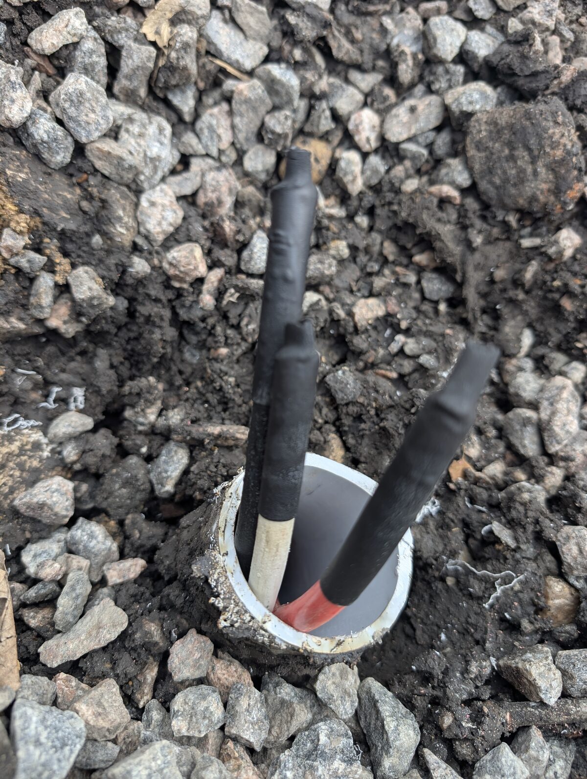
Why This Type of Work Matters
Telecom companies, tower management firms, and infrastructure contractors need electricians who understand commercial and industrial electrical systems – beyond residential wiring. This type of work requires:
- Knowledge of utility coordination procedures – You can’t just pull a meter. The utility company needs to be involved in the disconnection process, and the timeline needs to be coordinated so the site isn’t left in an unsafe intermediate state.
- Inspector relationship and code knowledge – Understanding when a permit is required (and when it isn’t) saves the client unnecessary costs and delays. We confirmed the jurisdictional requirements before quoting the project.
- Proper termination practices – Cutting wires and walking away isn’t acceptable. Service conductors must be individually insulated and the raceway must be sealed to prevent future hazards – even years down the road.
- Access protocol compliance – Cell tower compounds are secured facilities with gate codes, locks, and access restrictions. We follow all site access protocols and leave the compound locked and secured exactly as we found it.
Commercial and Industrial Electrical Services in West Central Minnesota
Bright Haven Electric provides commercial and industrial electrical services throughout West Central Minnesota, including telecom infrastructure, agricultural facilities, and commercial buildings. We handle the full scope of commercial electrical work – from inspector and utility coordination through final cleanup and documentation.
If you’ve a commercial electrical project in the Olivia, Willmar, Marshall, Montevideo, or greater Renville County area, contact us or call (320) 321-9699 to discuss your project.
Oxide Inhibitor on Aluminum Connections – Field Video
See a side-by-side comparison from a live CT cabinet showing treated vs. untreated aluminum terminations. The difference is impossible to ignore.
Proper oxide inhibitor aluminum connections are essential to the performance and longevity of service entrance equipment; however, many installations skip this critical step entirely. Aluminum is the standard conductor material for feeders, service entrance cables, and utility-supplied conductors throughout West Central Minnesota. Residential 200-amp service upgrades, commercial feeder runs, and utility drops all rely on aluminum conductors. There’s nothing wrong with aluminum at these sizes – it’s lighter, less expensive, and performs reliably when terminated correctly.
The critical word in that sentence is correctly. Aluminum forms a layer of aluminum oxide the moment it contacts air, and that oxide layer creates the problem. Aluminum oxide is an electrical insulator – the same compound used in ceramic resistors and sandpaper. When it builds up inside a mechanical lug, it increases resistance at the connection point. That resistance generates heat, which in turn accelerates further corrosion. As a result, the connection degrades in a self-reinforcing cycle that eventually leads to overheating, arcing, or outright failure.
Fortunately, the prevention is straightforward: apply an oxide inhibitor – a conductive compound such as Penn-Union CUAL-GEL (castor oil-based and safe near plastics) – to the aluminum strands before inserting them into the lug. The compound displaces oxygen, breaks through existing oxide skin, and keeps the metal-to-metal contact clean for the life of the connection. Most lug manufacturers specify oxide inhibitor in their installation instructions, and the National Electrical Code supports this practice through 110.3(B) and 110.14. The entire application takes thirty seconds per termination.
We recorded this video inside a CT (current transformer) cabinet during a routine service call. It clearly shows both sides of the equation – in the same enclosure, on the same day.
Oxide Inhibitor Aluminum Connections – What the Video Shows
This CT cabinet sits between the utility’s metering equipment and the client’s electrical service. Two sets of aluminum conductors terminate inside – the utility supply on top and the client load connections on the bottom. Although both share the same cabinet, environment, and aluminum conductor material, the only difference is how the installer made each termination.
Utility Side – With Oxide Inhibitor
- DeOx compound is clearly visible – a dark, heavy application coating the exposed aluminum strands entering the mechanical lugs
- Zero white oxidation – the aluminum retains its original metallic appearance under the compound
- Clean, solid terminations – no corrosion, no discoloration, no degradation of the conductor strands
- The compound seals out oxygen and moisture, preventing aluminum oxide formation at the contact surface
Client Side – No Oxide Inhibitor
- No compound applied – bare aluminum strands inserted directly into the mechanical lugs
- Significant white powdery buildup – aluminum oxide has accumulated on the conductor strands inside the lug body
- Active degradation – the oxidation is visibly degrading the conductor material and compromising the contact surface
- Environmental debris is also present – the unprotected connection attracted moisture and contaminants
This isn’t a laboratory demonstration. Both sets of conductors have been in service, in the same enclosure, exposed to the same temperature swings, humidity, and environmental conditions. On the utility side, the crew applied oxide inhibitor to protected aluminum connections from day one. The installer on the client side, however, didn’t apply any compound. The contrast speaks for itself.
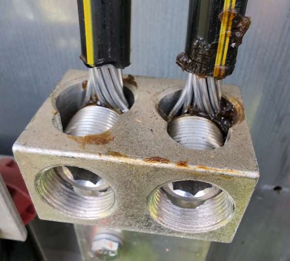
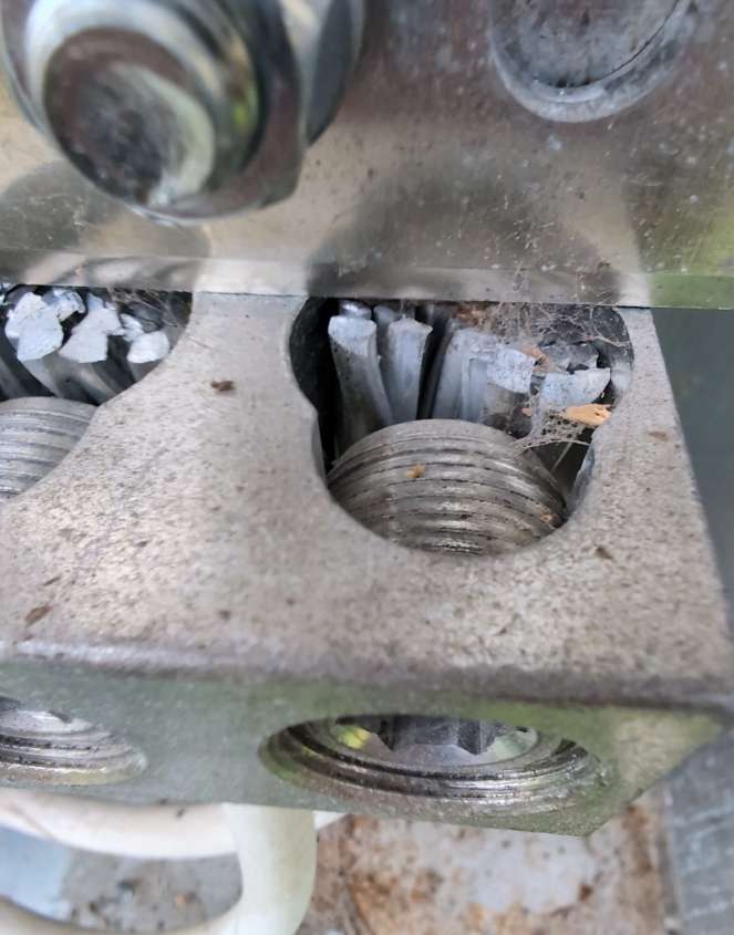
Why Oxide Inhibitor Matters on Aluminum Connections
Aluminum reacts with atmospheric oxygen almost instantly when exposed. The resulting aluminum oxide layer (Al₂O₃) is extremely thin – just nanometers – but it’s electrically significant. Specifically, aluminum oxide has a resistivity of approximately 10¹⁴ ohm-centimeters. By comparison, copper oxide has a resistivity several orders of magnitude lower and remains somewhat conductive. In other words, aluminum oxide is, for all practical purposes, a ceramic insulator.
The Oxide Layer Problem
When aluminum terminates in a mechanical lug without oxide inhibitor, an oxide layer forms at the contact surface between the conductor and the lug body. Current must then pass through this insulating barrier. As the oxide thickens over time, connection resistance increases accordingly. The increased resistance converts electrical energy to heat – Joule heating (I²R) – which accelerates further oxidation. Consequently, the process becomes progressive and self-reinforcing.
Progressive FailureThermal Cycling Compounds the Problem
Aluminum has a higher coefficient of thermal expansion than the copper or tin-plated connectors it terminates in. Every load cycle – morning coffee pot, evening HVAC – heats and cools the connection. The aluminum expands and contracts more than the lug. Over thousands of cycles, this differential movement loosens the mechanical bond and introduces micro-gaps where fresh oxide forms. This is the same fundamental mechanism behind high-resistance connections that cause overheating in panels and service equipment.
Micro-Gap FormationWhat Oxide Inhibitor Does
Oxide inhibitor compounds serve two functions. First, the compound contains suspended metallic particles (typically zinc or copper) that are abrasive enough to scrape through the existing oxide skin during insertion and torquing. Second, a carrier compound seals the connection from oxygen and moisture, preventing new oxide from forming. The result is a clean, low-resistance, gas-tight connection that maintains its integrity for the life of the installation. We recommend non-petroleum-based compounds like Penn-Union CUAL-GEL, which uses a castor oil carrier that’s chemically safe near thermoplastic components. Petroleum-based products exist (DeOx, Noalox, Penetrox), but their carrier chemistry introduces material compatibility concerns that make them unsuitable for many common installation environments – more on that below.
Permanent ProtectionGetting Oxide Inhibitor Aluminum Connections Right
Applying oxide inhibitor isn’t as simple as squeezing compound onto a wire and tightening a lug. In practice, the type of compound, the surface preparation, and the torque values all interact. Getting any one of these wrong can create a termination that appears “treated” but remains compromised underneath. These are the details that separate competent installation from checkbox installation.
Material Compatibility – Not All Compounds Are Safe Near Plastics
The dark compound visible on the utility-side connections in our video is a petroleum-based oxide inhibitor. While it’s effective at preventing oxidation, it isn’t universally appropriate. Technical documentation from manufacturers including Schneider Electric (Square D) and Siemens explicitly warns against using petroleum-based deoxidizers near plastic components. Petroleum degrades the structural integrity of thermoplastic breaker casings and wire insulation over time, which can lead to cracking, embrittlement, and potential failure of the plastic housing itself. Therefore, for terminations near or inside breaker panels, load centers, and any equipment with thermoplastic enclosures, always specify a non-petroleum-based oxide inhibitor – such as Penn-Union CUAL-GEL – that’s chemically compatible with plastics. Additionally, consult the equipment manufacturer’s installation documentation to confirm which compounds are approved for use with their products.
Manufacturer WarningTorque Dynamics – Dry Values vs. Wet Values
Fastening specifications published by lug manufacturers are dry torque values – calibrated for bare, unlubricated threads and contact surfaces. However, applying oxide inhibitor introduces lubrication, which creates a wet torque scenario where the same torque wrench reading produces significantly higher clamping force than intended. Because the lubricant reduces friction between the fastener threads and the lug body, the bolt tightens further for the same applied torque. As a result, over-tensioning crushes the softer aluminum strands, damages the lug seat, and can cause mechanical failure of the termination over time. To avoid this, consult the manufacturer’s specifications to determine whether torque values need adjustment when an inhibitor is present. Some lug manufacturers publish separate wet torque specifications. If no wet value is provided, the standard guidance is to reduce applied torque by approximately 25% from the published dry value – but always defer to the specific manufacturer’s documentation.
Torque Adjustment RequiredSurface Preparation – Brush First, Apply Immediately
Oxide inhibitor applied over existing oxide traps the resistance underneath. If a compound covers a conductor that has already formed an oxide layer, it will seal that insulating layer in place rather than eliminating it. Instead, the correct procedure is to mechanically wire-brush the unplated aluminum strands to remove existing oxide, exposing fresh, bright metal – and then immediately apply the inhibitor before the aluminum re-oxidizes. Because aluminum oxide begins reforming within seconds of air exposure, the window between brushing and compound application must be as short as possible. This is why experienced electricians keep the compound open and ready before they start brushing – brush, coat, insert, torque. No pauses. Although the metallic particles suspended in the compound perform additional abrasive scrubbing during insertion, they can’t compensate for a thick, established oxide layer that was never removed.
Sequence MattersCommon Mistakes We Find in the Field
- Petroleum-based compound smeared on or near plastic breaker casings – slowly degrading the thermoplastic housing, which may not be discovered until the component fails during a maintenance event or fault
- Dry torque values applied to lubricated terminations – resulting in over-compressed aluminum strands and premature lug failure, especially on #4 through 4/0 conductors
- Compound applied over existing oxide – the termination appears “treated” on visual inspection, but the oxide insulating layer remains intact underneath the compound, still generating heat under load
It Is Not Optional – Code and Manufacturer Requirements for Oxide Inhibitor
Applying oxide inhibitor to aluminum connections isn’t merely a best practice suggestion – it’s backed by multiple sources of authority. Skipping this step, whether out of carelessness, ignorance, or cost-cutting, creates a connection that will inevitably degrade. The question isn’t whether it will fail but when.
What the Code and Manufacturers Require
- NEC 110.14 – Connection Integrity: All connections must be made in a manner that ensures a low-resistance, durable electrical bond. Aluminum connections that oxidize and increase in resistance violate the fundamental performance requirement of this section.
- Lug Manufacturer Instructions: Most major manufacturers of mechanical lugs rated for aluminum – including Ilsco, Burndy, Panduit, and NSi – include oxide inhibitor application in their listed installation instructions. Per NEC 110.3(B), equipment must be installed in accordance with its listing and labeling. Where the manufacturer specifies oxide inhibitor, skipping it means the termination wasn’t made per the listed instructions.
- Utility Standards: Most electric cooperatives and investor-owned utilities in Minnesota require oxide inhibitor on all aluminum connections in metering and service entrance equipment. The utility-side connections in our video demonstrate this standard being followed correctly.
- UL 486A-486B: The UL standard governing wire connectors references the use of joint compounds for aluminum connections as part of the tested and listed assembly. Omitting the compound means the connection hasn’t been made per the tested configuration.
“The installation sheet is right there in the box. Most lug manufacturers specify oxide inhibitor on aluminum. When we open a panel and find bare aluminum stuffed into a lug with no compound, we know that installer either didn’t read the instructions or chose to ignore them. Either way, the connection is compromised – and it will get worse over time, not better.” – Chadwick Ferguson, Master Electrician & Co-Owner, Bright Haven Electric LLC
What Happens When Oxide Inhibitor on Aluminum Connections Is Skipped
The untreated connections in our video aren’t an edge case. In fact, we find aluminum terminations without oxide inhibitor regularly – in residential panels, commercial switchgear, agricultural disconnects, and CT cabinets across our service area. The consequences range from nuisance problems to catastrophic failure.
Overheated Connections and Fire
As resistance increases at the oxidized termination, the connection generates heat under load. Mechanical lugs carry a maximum temperature rise rating, and an oxidized connection can exceed that threshold. When it does, it softens the conductor, degrades the lug, and can potentially ignite adjacent insulation or enclosure materials. According to forensic investigations, high-resistance connections rank among the top causes of electrical fires.
Fire HazardVoltage Drop and Equipment Damage
A high-resistance termination creates a measurable voltage drop at the connection point. Sensitive electronics, motor compressors, and HVAC equipment are designed to operate within a narrow voltage window. Chronic low voltage from a degraded service connection shortens equipment life, increases operating costs, and can cause erratic behavior – flickering lights, tripping breakers, and intermittent faults that are difficult to diagnose without thermal imaging.
Hidden Energy LossConnection Failure Under Load
In the worst case, the accumulated oxide and thermal cycling cause the conductor to lose effective contact inside the lug. Under heavy load – a well pump starting, an air conditioner compressor engaging – the connection can arc as current jumps across the micro-gaps. Arcing inside an enclosed panel or CT cabinet produces intense heat, vaporized metal, and potentially an arc flash event. This is a serious safety hazard for anyone working near or opening the enclosure.
Arc Flash RiskImportant Distinction – Feeders vs. Branch Circuit Aluminum
- This article discusses feeder-sized and service entrance aluminum conductors (typically #4 AWG and larger) terminated in mechanical lugs – standard practice in modern electrical systems
- Branch circuit aluminum wiring (15A and 20A circuits using #12 and #10 AWG aluminum, common in homes built 1965 – 1973) is an entirely different problem with different solutions – see our guide on aluminum wiring remediation
- Oxide inhibitor on feeder terminations is required by manufacturer instructions and code – it isn’t a remediation, it’s standard installation practice
How to Fix Oxide Inhibitor Aluminum Connections That Were Done Wrong
If your service equipment, CT cabinet, or panel has aluminum terminations without oxide inhibitor, the fix is straightforward – but it requires a licensed electrician. A qualified professional must de-energize the circuit first, and in many cases, this means coordinating a utility disconnect.
Step-by-Step Remediation for Untreated Aluminum Connections
Proper Remediation Procedure
- De-energize the equipment – the feeder or service must be disconnected. In a CT cabinet, this requires coordination with the serving utility to pull the meter or disconnect upstream.
- Open each mechanical lug – remove the conductor from the lug body. Inspect the conductor strands and the lug contact surface for damage, pitting, or excessive corrosion.
- Select the correct compound – we recommend a non-petroleum-based inhibitor such as Penn-Union CUAL-GEL (castor oil-based) as the default for all aluminum terminations. It’s chemically compatible with thermoplastic breaker casings, wire insulation, and all enclosure materials. Petroleum-based compounds (DeOx, Penetrox) degrade plastics over time per Schneider Electric and Siemens technical documentation – avoid them near breaker panels, load centers, and any thermoplastic components. Always verify compound compatibility with the equipment manufacturer’s documentation.
- Wire-brush and apply immediately – mechanically wire-brush all unplated aluminum strands until fresh, bright metal is exposed. Have the oxide inhibitor open and ready. Apply the compound immediately after brushing – aluminum re-oxidizes within seconds. Don’t brush, set the conductor down, and return to it later. Brush, coat, insert, torque – without pauses.
- Torque to the correct specification – re-insert the conductor into the lug and torque using a calibrated torque tool. Published lug torque values are dry specifications. The oxide inhibitor lubricates the connection, creating a wet torque condition. Consult the manufacturer’s documentation for wet torque values. If no wet specification is published, reduce applied torque by approximately 25% from the dry value. Over-torquing crushes aluminum strands and damages the lug seat – a failure mode that’s invisible until the connection overheats under load.
- Inspect and document – verify all connections, confirm torque values, note the compound product used, and document the work for the property owner’s records and future reference.
Overall, the entire procedure takes under an hour for a standard residential service. The cost is minimal compared to the consequences of letting oxidized connections remain in place. This is exactly the kind of issue we identify during a panel inspection or electrical safety audit.
Serving West Central Minnesota
Bright Haven Electric LLC performs panel inspections, service equipment evaluations, and aluminum termination corrections across our 10-county service area in West Central Minnesota. We carry thermal imaging equipment to identify high-resistance connections that aren’t yet visible to the naked eye – catching problems in the early stages before they become hazardous.
Whether it’s a CT cabinet missing oxide inhibitor, a 200-amp panel with improperly torqued lugs, or a full service area inspection – we do this work every day. If you’ve aluminum service conductors (and nearly every property does), a 15-minute termination check could prevent a serious problem down the road.
Concerned About Your Aluminum Connections?
Schedule a panel inspection or service equipment evaluation. We check every termination, apply thermal imaging, and document everything – so you know exactly what condition your electrical connections are in.
Spring Cabin Electrical Startup Guide
A 12-point safety checklist from a licensed Minnesota electrician. Don’t flip the main breaker without inspecting the system first.
Every spring, thousands of Minnesota cabin owners arrive, open the electrical panel, and throw the main breaker. Power comes on. Lights work. Everything seems fine – until it isn’t. A mouse chewed through Romex behind the kitchen wall. Freeze-thaw cracked an exterior outlet box. A dock GFCI failed silently over winter. Zero shock protection near water.
A proper spring cabin electrical startup takes about 30 minutes. It prevents house fires, shocks, and thousands of dollars in appliance damage. This guide matches the same 12-point inspection our team performs on seasonal properties across West Central Minnesota. You can do most of it yourself – and you’ll know when to call a pro.
Has your cabin been idle since last fall? Don’t skip this. The electrical system endured a full Minnesota winter – no heat, no ventilation, no one watching. Treat the startup as the safety procedure it’s.
Why a Spring Cabin Electrical Inspection Matters
Your primary residence stays heated, occupied, and monitored year-round. Your cabin doesn’t. From November through April, it endures -30°F to 40°F temperature swings, ice loading, humidity shifts, and uninvited guests – rodents, squirrels, and raccoons – who chew your wiring for nesting material. Here is what that does:
Freeze-Thaw Damage
Repeated freeze-thaw cycles crack outlet boxes, shift conduit connections, and destroy weatherproof covers. Moisture trapped in a junction box since November loosens wire connections and corrodes terminals over five months. The service entrance and meter base are most vulnerable – ice loading can shift the mast away from the building.
Fire & Shock HazardRodent Wiring Damage
Mice and squirrels chew through Romex sheathing to access copper – or to wear down their teeth. A chewed wire in a wall cavity is an arc fault waiting to happen. That stripped insulation was the only barrier preventing a short circuit. One spark inside a wall full of mouse-nest material is all it takes to start a fire.
Arc Fault & Fire RiskPower Surge Exposure
If utility service stayed connected over winter, your cabin absorbed every outage, brownout, and voltage spike from ice storms. Without a whole-house surge protector, those transients hit your wiring and appliances directly. A damaged compressor or pump board may not show symptoms until you use the appliance.
Hidden Appliance DamageMoisture Intrusion
Unheated cabins accumulate condensation on cold surfaces – inside panels, junction boxes, and outlet enclosures. Moisture on bus bars and breaker terminals causes corrosion and arcing. If water entered through a damaged roof or window, a professional must inspect the wiring before you energize those circuits. Water and electricity never mix.
Do Not Energize Wet Circuits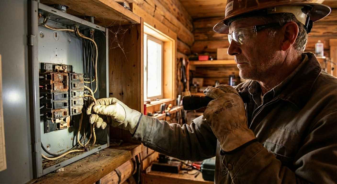
The 12-Point Spring Cabin Electrical Startup Checklist
This is the same checklist our crew follows for every spring cabin electrical startup. Work through it in order – each step builds on the last. Don’t flip breakers until the visual inspections are complete.
Phase 1: Visual Inspection (Before Touching Breakers)
Inspect First – Power On Later
Complete these steps before anyone sleeps in the cabin. If any step reveals a problem, stop and call a licensed electrician.
- Walk the exterior and inspect the service entrance. Check the weatherhead, service mast, and meter base for ice damage or corrosion. Look for sagging wires, cracked brackets, or gaps between the mast and building. If the mast has shifted, don’t energize – your utility may refuse reconnection until a contractor repairs it.
- Inspect the electrical panel before touching any breakers. Open the panel door. Look for moisture, corrosion, rust on bus bars, rodent evidence, and burning smells. Confirm all breakers are OFF. Standing water inside the panel? Stop immediately and call a licensed electrician.
- Check for rodent damage in accessible wiring areas. Inspect the attic, crawlspace, and basement for chewed insulation, droppings, and nesting material. Mice chew Romex consistently. The damage is often hidden. Look behind appliances and inside utility closets.
- Examine all exterior outlets and covers. Open every weatherproof cover on outdoor receptacles. Check for cracks, corrosion, and moisture. Replace damaged covers before energizing those circuits. Dock and lakeshore outlets are most vulnerable.
Phase 2: Gradual Power-Up
Energize Step by Step
Turn on circuits one at a time. This isolates faults and prevents cascading damage.
- Turn on the main breaker only – leave branch circuits off. Listen for buzzing, humming, or arcing at the panel. If the main trips immediately, don’t re-engage it. A downstream fault requires professional diagnosis.
- Activate branch circuits one at a time. Turn on each breaker and wait 15 – 30 seconds. Start with lighting, then outlets, then heavy loads (well pump, water heater, HVAC). If a breaker trips, leave it off and move on.
- Test every GFCI outlet and GFCI breaker. Press TEST on every GFCI outlet – kitchen, bath, exterior, garage, dock, and any outlet near water. It should trip instantly. Press RESET to restore. A GFCI that won’t trip has failed. Replace it before using that circuit.
- Test all smoke detectors and CO alarms. Press the test button on every smoke and CO detector. Replace all batteries – even working ones. Batteries stored unheated for six months are unreliable. Replace detectors older than 10 years (smoke) or 7 years (CO).
Phase 3: Systems, Dock, and Final Checks
Verify Critical Systems
These final steps cover infrastructure, waterfront safety, and documentation.
- Verify well pump and septic circuits. If you’re on a private well and septic system, energize those circuits. Confirm the well pump builds pressure normally. Short cycling means a pressure switch or bladder problem. Check the control box for tripped overloads.
- Inspect dock and shoreline electrical equipment. Before energizing dock, boat lift, or shoreline circuits, inspect all wiring and receptacles visually. Look for storm damage and ice-heaved posts. Dock circuits require GFCI protection – confirm it works before anyone enters the water.
- Check surge protection and test appliances. A whole-house surge protector with a green LED is active. Red or off means the module absorbed a surge – replace it. Plug in appliances one at a time. Watch for issues: a fridge that runs but won’t cool, a heater that trips, or flickering lights.
- Document everything. Write down issues, label tripped breakers, and note any fixtures that failed. Record the inspection date for next year’s baseline. If you found problems, call an electrician before occupying the cabin. Don’t use faulted circuits.
“The worst cabin fires we respond to start the same way – someone opens up in the spring, throws the main breaker without looking first, and energizes a circuit that has been compromised all winter. Thirty minutes of inspection prevents that. Every single time.” – Chadwick Ferguson, Master Electrician & Co-Owner, Bright Haven Electric LLC
When to Stop and Call a Licensed Electrician
Most cabin owners can safely complete this checklist. But some conditions require a licensed professional. Attempting DIY repair risks electrocution, fire, or further damage. If you encounter any of these, stop, turn off the circuit, and call us:
Stop – Call an Electrician Immediately
- Standing water inside the electrical panel – indicates a serious moisture intrusion path that has compromised the service equipment
- Burn marks, melted plastic, or burning smell at the panel – evidence of arcing or overheating that occurred while the cabin was unoccupied
- Service mast physically shifted or separated from the building – the utility connection is compromised and may need to be rebuilt before reconnection
- Main breaker trips immediately upon engagement – indicates a downstream fault (short circuit or ground fault) that must be located and repaired
- Any breaker trips repeatedly when activated – the circuit has a persistent fault, potentially from rodent damage, water intrusion, or a failed appliance
- Outlets or switches that feel warm to the touch – heat at a device indicates a loose connection, overloaded circuit, or damaged wiring behind the device
- Visible rodent damage to wiring – chewed insulation on any conductor is a fire hazard and requires professional repair, not tape
- Buzzing, crackling, or arcing sounds – audible electrical noise from walls, panels, or outlets indicates an active fault that could ignite at any time
- GFCI outlets that won’t trip or reset – failed ground fault protection near water is a life-threatening shock hazard, especially on dock and exterior circuits
Important Reminder – Do Not Use Damaged Circuits
- Don’t re-engage a breaker that has tripped twice on the same circuit – the fault is real and it won’t fix itself
- Don’t use electrical tape to repair chewed or damaged wiring – the repair must meet NEC code requirements
- Don’t stand in water or on damp ground while operating electrical equipment
- If you’re unsure about any condition you find, leave the circuit off and let a professional evaluate it – that’s always the right call
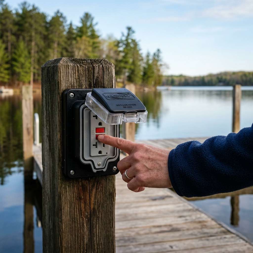
Remote Monitoring – Protect Your Cabin Year-Round
The best time to prevent winter damage is during the winter – not after. Modern remote monitoring lets you watch your property from anywhere. Know about problems before they become emergencies. Here are the systems we install for cabin owners:
WiFi Freeze Alarms & Temperature Monitors
A WiFi-connected temperature sensor sends an alert to your phone when the cabin interior drops below a set threshold – typically 40°F. This gives you time to respond before pipes freeze and burst, which prevents both water damage and the electrical hazards that follow when water contacts wiring. Units like the Temp Stick and MarCELL work on cellular networks where WiFi is unavailable.
Prevent Freeze DamageSmart Thermostats & HVAC Monitoring
A smart thermostat lets you maintain a 45 – 50°F setpoint remotely to prevent freezing. It alerts you if the system stops or temperatures drop. Combined with off-peak rates from your electric cooperative, this approach is surprisingly affordable.
Remote Climate ControlPower Outage Notification
A cellular-based power monitor alerts you when utility power is lost at the cabin – and again when it’s restored. Knowing about an outage in real time lets you assess the risk: a 2-hour outage in October is inconsequential, but a 48-hour outage in January with no heat backup means frozen pipes and potential water damage to your electrical system. Early notification gives you options.
Real-Time AlertsSecurity Cameras & Smart Sensors
Internet-connected cameras and door/window sensors provide both security and property monitoring. Motion alerts let you know if someone – or something – is at the cabin when it should be empty. Some camera systems also detect water leaks and unusual temperature changes. We install wired and wireless camera systems designed for seasonal properties with intermittent connectivity.
Security & MonitoringNo Internet at Your Cabin? No Problem
Many cabins in Big Stone, Lac qui Parle, and Pope counties lack reliable broadband. Cellular devices like the MarCELL HW-003 use 4G LTE – no WiFi or landline needed. They run on AC power with battery backup. If power fails, they alert you until the battery depletes. We help cabin owners choose the right solution.
Bright Haven Electric installs and configures remote monitoring systems as part of our seasonal cabin electrical services. We handle the electrical connections, device placement, and network configuration so you get reliable alerts without the guesswork.
Closing the Loop – Fall Shutdown Matters Too
A proper spring startup is dramatically easier when the cabin was properly shut down the previous fall. Here is the short version of what a good fall electrical shutdown looks like – we’ll publish a complete fall shutdown guide before the end of the season:
Fall Shutdown Essentials
- Turn off all branch circuit breakers individually – don’t just kill the main; turning off individual breakers lets you verify each one in the spring
- Unplug all appliances and electronics – prevents surge damage from winter outages and eliminates phantom loads
- Drain water systems and winterize plumbing – prevents pipe bursts that damage the wiring in affected areas
- Set mouse traps and seal entry points – rodent prevention is the single most effective way to protect cabin wiring over winter
- Install or verify remote monitoring equipment – so you know about problems before they become emergencies
- Test and replace smoke and CO detector batteries – even if the cabin will be empty, working detectors protect against an undetected electrical fire
- Document your shutdown – take photos of the panel (breakers off), record which circuits were active, and note any maintenance items for spring
Cabin Country Electricians – West Central Minnesota
Bright Haven Electric LLC provides spring cabin inspections, remote monitoring, and full seasonal electrical services across West Central Minnesota lake country. Our service area has some of the highest seasonal property concentrations in the state. We understand the unique electrical challenges that come with them.
We serve seasonal homeowners at properties on Big Stone Lake, Lac qui Parle Lake, Lake Emily, Pomme de Terre Lake, Lake Minnewaska, Lake Andrew, Eagle Lake, and dozens of smaller lakes and seasonal communities across our 10-county service area.
If you need a full spring startup inspection, a single GFCI replacement on the dock, or a complete remote monitoring system to protect your cabin year-round – we’re here. We live in this community, we serve this community, and we take care of it the same way we take care of our own property at Bright Haven Farm.
Schedule Your Spring Cabin Startup Inspection
Opening your cabin this spring? Let a licensed electrician verify that your electrical system survived the winter before you flip the main breaker. Fast. Thorough. One less thing to worry about on opening weekend.